
3D printer nozzle

A technology of 3D printers and nozzles, which is applied in coating devices, additive processing, etc., can solve problems such as nozzle clogging, nozzle heat dissipation effect is not obvious, and printing accuracy is affected, so as to reduce clogging, good heat dissipation effect, and easy operation easy effect

Inactive Publication Date: 2018-12-14
芜湖诺磊自动化科技有限公司
View PDF0 Cites 0 Cited by
  • Summary
  • Abstract
  • Description
  • Claims
  • Application Information

AI Technical Summary

Problems solved by technology

However, the 3D printers of the prior art are prone to clogging in the nozzle when printing and spraying materials, and the nozzle needs to be disassembled, replaced and maintained many times. Therefore, an easily detachable 3D printer nozzle is very necessary.
In addition, the heat dissipation effect of the nozzle is not obvious, which affects the printing accuracy

Method used


Image

  • 3D printer nozzle

Examples


Embodiment Construction

[0015] The following will clearly and completely describe the technical solutions in the embodiments of the present invention with reference to the accompanying drawings in the embodiments of the present invention. Obviously, the described embodiments are only some, not all, embodiments of the present invention. Based on the embodiments of the present invention, all other embodiments obtained by persons of ordinary skill in the art without making creative efforts belong to the protection scope of the present invention.

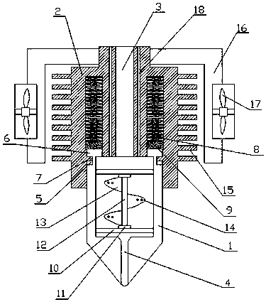
[0016] figure 1 Shown is a schematic diagram of the overall structure of the 3D printer nozzle in this embodiment. A 3D printer nozzle includes a feeding cylinder 2 and a detachable head 1 detachably fixed at the lower part of the feeding cylinder 2. A discharge chamber is arranged inside the detachable head 1. A throat 3 is arranged in the middle of the feeding cylinder 2, and the throat 3 communicates with the discharge chamber, and a discharge port 4 is arr...


PUM


Abstract

The invention relates to a 3D printer nozzle. The 3D printer nozzle comprises a feeding barrel and a dismounting head detachably fixed to the lower portion of the feeding barrel. A discharging cavityis arranged in the dismounting head. A throat pipe is arranged in the middle of the feeding barrel and communicates with the discharging cavity. A discharging port is arranged at the bottom of the dismounting head. Arc-shaped sliding chutes are concaved inwards on the outer side wall of the upper portion of the dismounting head. Limiting blocks are arranged on the upper portions of the arc-shapedsliding chutes. Clamping pins matched with the arc-shaped sliding chutes are convexly arranged on the inner side wall of the lower portion of the feeding barrel. The arc-shape arrangement of the limiting blocks is match with the lower portion of the feeding barrel. The lengths of the limiting blocks are smaller than the distance between the clamping pins. The clamping pins can be embedded into thearc-shaped sliding chutes after the dismounting head rotates, and the heights of the arc-shaped sliding chutes are larger than the heights of the clamping pins. Compression channels are arranged on the upper portions of the clamping pins. Compression springs are arranged in the compression channels. Sliding blocks are arranged on the end portions, facing the dismounting head, of the compression springs. The 3D printer nozzle is easy to dismantle and good in heat dissipation effect.

Description

technical field [0001] The invention relates to the technical field of 3D printers, in particular to a 3D printer nozzle. Background technique [0002] The idea of ​​3D printing originated in the United States at the end of the 19th century, and was developed and promoted in the 1980s. The biggest difference between a 3D printer and a traditional printer is that the "ink" it uses is a real raw material, and there are many forms of stacked thin layers. It is often used to manufacture models in mold manufacturing, industrial design and other fields, and is gradually used in the direct manufacture of some products. The actual forming accuracy of a 3D printer is mainly affected by factors such as nozzle temperature, forming chamber temperature, material shrinkage performance, layer thickness, extrusion speed, filling speed, manufacturing and assembly accuracy of the printer itself, and vibration during work. However, the 3D printers of the prior art are prone to clogging in the...

Claims


Application Information

Patent Timeline
IPC IPC(8): B29C64/209B33Y30/00
CPCB29C64/209B33Y30/00
Inventor 丁稀林
Owner 芜湖诺磊自动化科技有限公司
Learn More