The connection method of continuous hot bending forming and closed welding process

A welding station and process technology, which is applied in the field of connection between continuous hot bending forming and closed welding process, can solve the problems such as difficulty in ensuring the shape of closed welding section, online closed welding of difficult high temperature components, and matching of forming speed of difficult hot bending machines, etc. Achieve the effects of improving production efficiency and welding quality, improving production efficiency, and ensuring the shape of the closed welding section

Active Publication Date: 2019-09-24
CISDI RES & DEV CO LTD
View PDF5 Cites 0 Cited by
  • Summary
  • Abstract
  • Description
  • Claims
  • Application Information

AI Technical Summary

Problems solved by technology

Furthermore, common and economical welding methods on the market today, such as submerged arc welding, TIG welding, MIG welding, MAG welding, etc., have low welding speeds (several meters per second), which are difficult to match with the forming speed of hot bending machines. match
Therefore, the current existing welding methods are difficult to achieve online closed welding of high temperature components, and only offline or sideline welding can be used to solve the closed welding of high temperature components
[0004] For the high-temperature formed components that are to be welded off-line or side-line, there is a large temperature drop between the continuous hot bending and the closed welding process, and the internal thermal stress caused by the temperature drop, as well as the thermal bending springback of the component itself, etc. These factors will cause the shape deformation of the component, which makes it difficult to guarantee the shape of the closed welding section

Method used


Image

  • The connection method of continuous hot bending forming and closed welding process
  • The connection method of continuous hot bending forming and closed welding process
  • The connection method of continuous hot bending forming and closed welding process

Examples


Embodiment 1

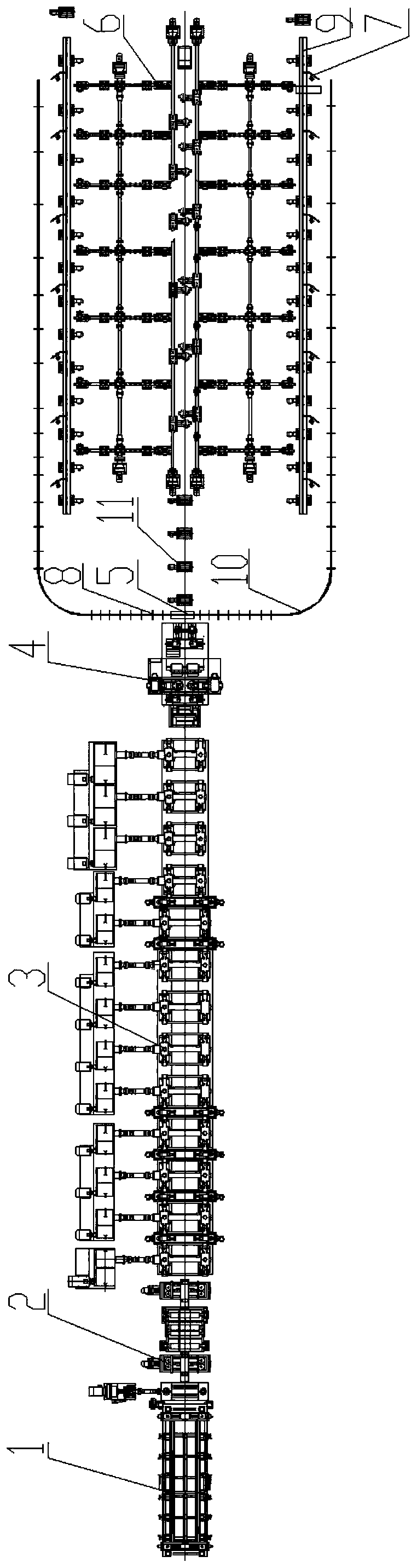
[0030] Such as figure 1 , 2 As shown, the feeding roller table 1, the centering device 2, the forming unit 3, the squeeze roller 4, the quick clamping device 5 that can release the clamp, the transfer device 6 and the welding equipment 7 are arranged in order along the component production direction, The raw steel plate is hoisted to the feeding roller table, enters the forming unit after the centering device, and then squeezed by the squeeze roller to form a closed steel member 9. When the head of the closed steel component exits the squeeze roller, during the operation of the component, the quick clamping device 5 quickly releases a set of clamps to clamp the high temperature component. As the closed steel component continues to be extruded, it will release after a certain distance. The second set, the third set...the Nth set of clamps clamp the high temperature components, and after each clamp 8 clamps and locks the high temperature components, the power source is quickly cut...

Embodiment 2

[0032] Such as image 3 , 4 As shown, the feeding roller table 1, the centering device 2, the forming unit 3, the squeeze roller 4, the quick clamping device 5 that can release the clamp, the transfer device 6 and the welding equipment 7 are arranged in order along the component production direction. The steel plate is hoisted to the feeding roller table, enters the forming unit after the centering device, and then squeezed by the squeeze roller to form a closed steel component. When the tail of the high-temperature component is completely out of the squeeze roller and stops, the quick clamping device 5 releases several sets of clamps 8 along the length of the component at the same time to clamp the high-temperature component. After the molded component is completely clamped, the power source is quickly cut off , And then the closed steel component with the clamp is restarted and transported to the transfer device, and then transferred to the welding station through the transfer...


PUM


Abstract

The invention discloses a linking method for continuous hot bending forming and closing welding work procedures, that is, a device capable of releasing a clamping hoop is arranged at the outlet end ofa continuous hot bending unit, so that the clamping hoop is used for performing clamping shape determining on a closing type steel component after being formed through the continuous hot bending unit, and then the closing type steel component subjected to clamping shape determining through the clamping hoop is conveyed to a welding station to be subjected to closing welding. The method can effectively solve the component shape deforming problem caused by the factors of the internal heat stress generated due to the temperature drop of the component and the self hot bending springback, and therefore the purpose of guaranteeing the closing welding end face shape is achieved. Flexible linking between the continuous hot bending unit and the welding station is further achieved, so that a wholeproduction line can be continuously arranged, athe production line is more continuous and compact, and the production efficiency and the welding quality can be improved easily.

Description

Technical field [0001] The invention belongs to the field of metal processing, and specifically relates to a method for joining continuous hot bending forming and closed welding procedures. Background technique [0002] When the heated or rolled strips (temperature between 600℃~850℃) are bent into square tubes, round tubes or other types of closed components by the continuous hot bending unit, the components will lose heat due to the temperature drop and roll cooling water. The existence of the heat factor that takes away the components will cause the difference in the initial bending temperature of the raw material strip in the longitudinal direction due to the difference in the deformation sequence. An excessively large initial deformation temperature difference will have a certain impact on the stability of the bending deformation of the unit. In order to improve the stability of the hot forming of the unit and reduce the temperature difference at the beginning of bending, the...

Claims


Application Information

Patent Timeline
Patent Type & Authority Patents(China)
IPC IPC(8): B23P13/02
Inventor 李宏图沈继刚杨军波张金刚邓玉孙
Owner CISDI RES & DEV CO LTD
Why Eureka
Try Eureka