


Quick Research
Generate reliable direction feasibility study reports for your R&D in just a few steps.

Technical Q&A
Discover and master advanced knowledge NOW. Basics, ideas, possibilities, all at once.

Find Solutions
As an expert in R&D theories, this can generate solutions to your technical problems instantly.

Evaluate Feasibility
Analyze your overall solution with one click, know your potential R&D risks in advance.

Monitor Landscape
Get weekly tech updates, stay abreast of the latest tech innovations and key insights.
A municipal power distribution device
A power distribution device, municipal technology, applied in substation/distribution device housing, substation/switchgear cooling/ventilation, substation/switch layout details, etc. The effect of improving heat dissipation, reducing temperature rise rate, and low cost
- Summary
- Abstract
- Description
- Claims
- Application Information
AI Technical Summary
Problems solved by technology
Method used
Image

Examples
Embodiment 1
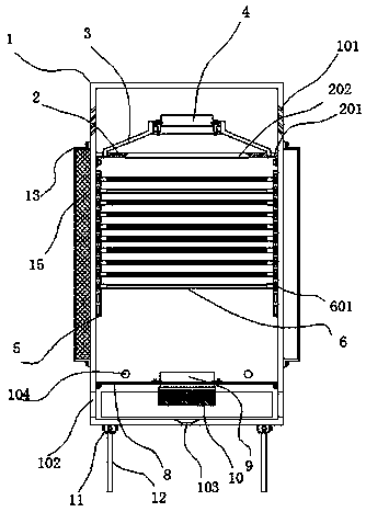
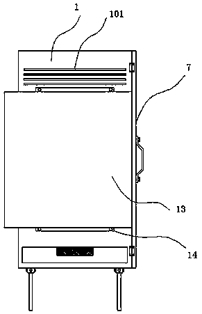
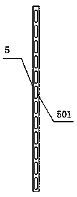
[0028] See Figure 1 to Figure 4 As shown, it includes a cabinet body 1. The cabinet body adopts cold-rolled plate SPCC, and a bracket plate 2 is screwed inside the cabinet body 1, and embedding grooves 201 are processed at the top left and right sides of the bracket plate 2. A bracket 3 is installed between the two embedded slots 201. The height of the bracket 3 is 20 cm. A fan 4 is installed in the middle of the bracket 3 to exhaust air. The fan 4 adopts the power distribution system to supply power. The support plate 2 has an air outlet groove 202 corresponding to the fan 4 on its surface. The left and right sides of the cabinet 1 are provided with first air outlet grooves 101 for discharging hot air outward. The end of 101 away from the inside of the cabinet 1 is arranged obliquely downwards, and side strips 5 are welded on the inner left and right sides of the cabinet 1, and the surface of the side strip 5 is evenly distributed with installation grooves 501, between the si...
Embodiment 2
[0031] See Figure 5 As shown, a support plate 121 is screwed to a position near the inner top of the cabinet body 1, and a filling gap is formed between the upper part of the support plate 121 and the inner top of the cabinet body 1, and the filling gap position is filled with heat insulation Cotton 131, insulation cotton also uses glass fiber cotton, the height of the filling gap is 20mm, by filling insulation cotton, heat insulation can be formed on the top of the cabinet. Between 11 and 14 o'clock every day, the temperature is higher when the sun is Therefore, the insulation cotton can reduce the introduction of heat at the top, thereby achieving the effect of heat insulation. At the same time, the top of the cabinet is subject to rain corrosion all the year round, so the probability of damage after corrosion will increase. Cotton can also play a temporary waterproofing effect, and water cannot penetrate through the support plate 121.
Embodiment 3
[0033] See Image 6 As shown, a wind baffle 131 is welded at the position of the inner rear end surface of the cabinet 1, and a ventilation gap is formed between the left and right sides of the wind baffle 131 and the inner side wall of the cabinet 1, and the cold air blown upward from the first fan passes through The wind baffle passes through the gap to both sides and then acts upward on the cooled power distribution system. By setting the wind baffle, the cold air can be conveyed upward from both sides, and the hot air can be discharged through the upper fan. Lower the internal temperature.
PUM
 Abstract
Description
Claims
Application Information
 - R&D Engineer
- R&D Manager
- IP Professional
- Industry Leading Data Capabilities
- Powerful AI technology
- Patent DNA Extraction
Browse by: Latest US Patents, China's latest patents, Technical Efficacy Thesaurus, Application Domain, Technology Topic, Popular Technical Reports.
© 2024 PatSnap. All rights reserved.Legal|Privacy policy|Modern Slavery Act Transparency Statement|Sitemap|About US| Contact US: help@patsnap.com