Photoelectric coupler lead frame limiting support

A technology of optocoupler and lead frame, applied in the direction of electric solid devices, circuits, electrical components, etc., can solve the problems of rust steel plate positioning dead, poor conductivity, etc., to increase conductivity, improve plating uniformity, avoid derailment or Effects of crush damage or greater friction

Inactive Publication Date: 2018-12-11
徐百灵
View PDF0 Cites 0 Cited by
  • Summary
  • Abstract
  • Description
  • Claims
  • Application Information

AI Technical Summary

Problems solved by technology

In order to ensure the electrical conductivity and the tension force during operation, stainless steel plates were generally used for positioning and electrical conduction, but due to the relatively rigid positioning of the rusted steel plates, and the partial deviation of the lead frame of the photocoupler during the advancement process, resulting in poor electrical conductivity

Method used


Image

  • Photoelectric coupler lead frame limiting support
  • Photoelectric coupler lead frame limiting support

Examples


Embodiment Construction

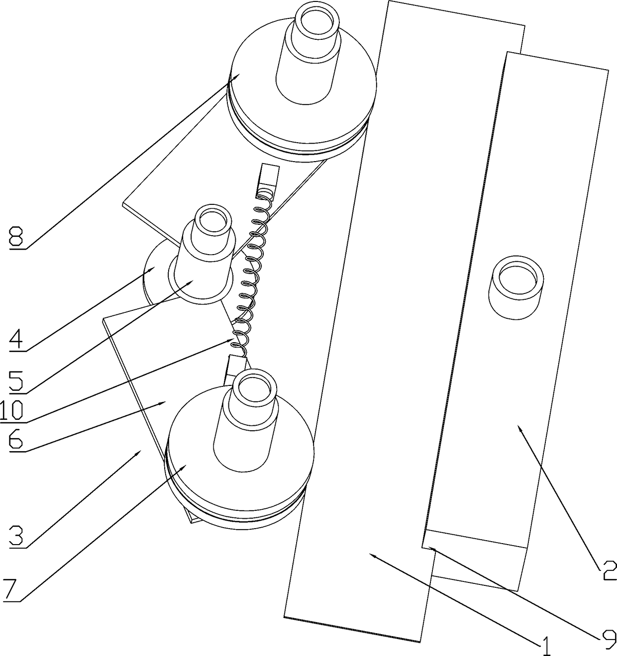
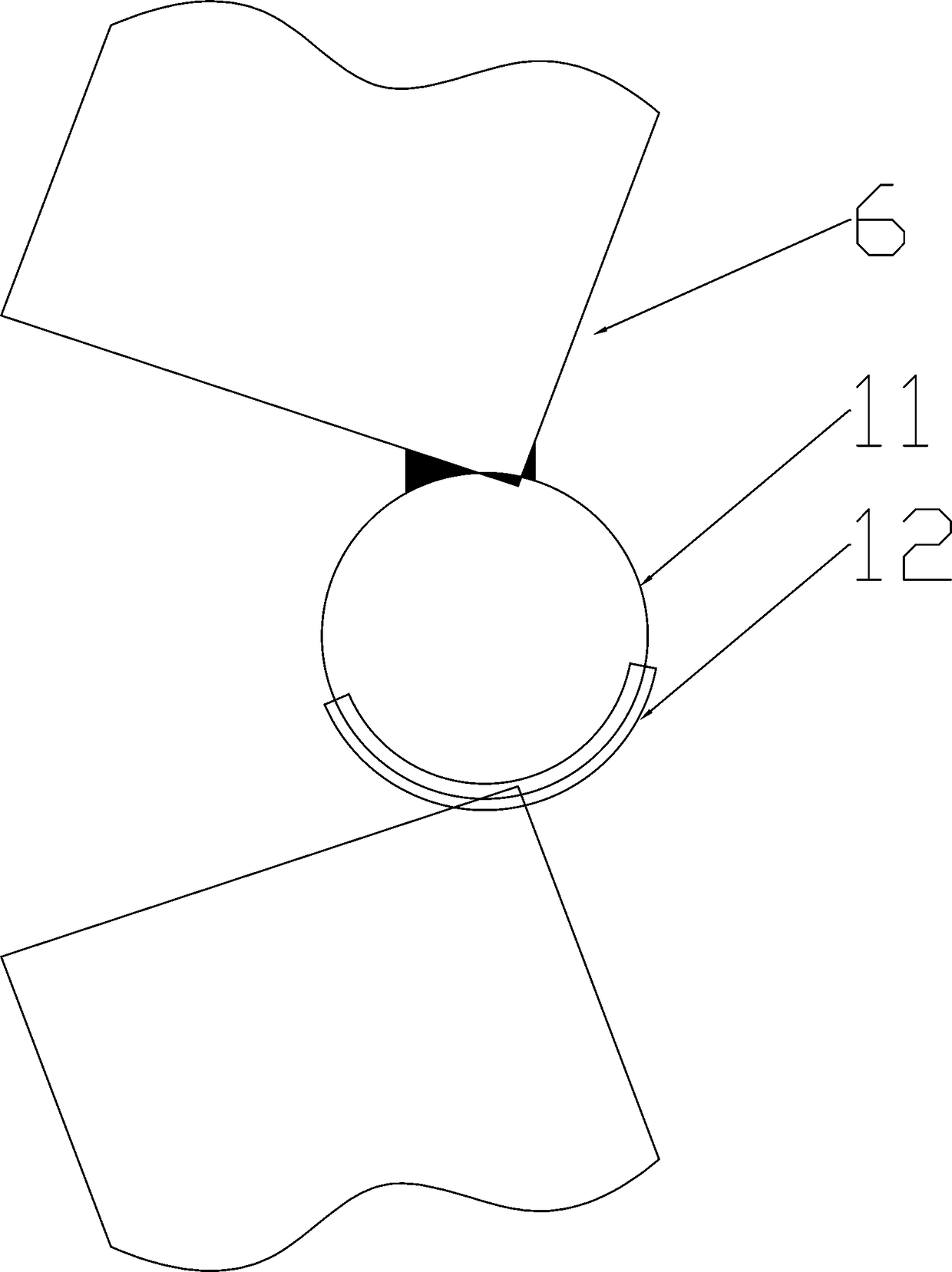
[0013] Such as Figure 1-2 As shown, a photocoupler lead frame limit bracket includes a positioning slide plate 2 arranged on one side of the photocoupler lead frame 1, the positioning slide plate 2 is made of copper, and a positioning chute 9 is opened on one side, and the positioning chute 9 is coated with a wear-resistant layer, and an adjustable sliding mechanism 3 is provided on the other side of the photocoupler lead frame 1, and the adjustable sliding mechanism 3 is made of stainless steel. The adjustable sliding mechanism 3 includes a fixed base 4, the fixed base 4 is provided with a rotating shaft 5, the rotating shaft 5 is provided with a ring groove, the arc sleeve 12 is arranged in the ring groove, and the arc sleeve 12 is socketed with the ring 11, It can rotate around the rotating shaft 5, and two positioning plates 6 are respectively connected to the edges of the arc sleeve 12 and the ring 11. The two positioning plates 6 are connected by a spring 10 and form a ...


PUM


Abstract

A photoelectric coupler lead frame limiting support comprises a positioning sliding plate arranged on one side of a lead frame of a photoelectric coupler, and an adjustable sliding mechanism arrangedon the other side of the lead frame of the photoelectric coupler, wherein the adjustable sliding mechanism comprises a fixed base; a rotating shaft arranged on the fixed base, and two positioning plates hinged to a rotating shaft and connected with each other through springs. A first rotating wheel and a second rotating wheel are symmetrically arranged on the two positioning plates respectively, positioning sliding grooves are formed in the first rotating wheel, the second rotating wheel and the positioning sliding plate. According to the photoelectric coupler lead frame limiting support, a flexible positioning conductive device is provided by the arrangement of an adjustable sliding mechanism, so that the good conductive performance is guaranteed.

Description

technical field [0001] The invention relates to the field of electroplating, in particular to a photocoupler lead frame limit bracket. Background technique [0002] The photocoupler lead frame is the basic frame of the photocoupler, which is used for welding chips and other components. The traditional lead frame has insufficient flatness and brightness, poor welding performance and corrosion resistance. Therefore, electroplating is required to improve the flatness and keep the brightness. During the silver plating process of the photocoupler lead frame, it needs to be continuously transported forward, passing through multiple electroplating baths to complete the electroplating. In order to ensure electrical conductivity and tension during operation, stainless steel plates were generally used for positioning and electrical conduction. However, due to the relatively rigid positioning of rusted steel plates, and the partial deviation of the photocoupler lead frame during advan...

Claims


Application Information

Patent Timeline
Patent Type & Authority Applications(China)
IPC IPC(8): H01L23/495
CPCH01L23/49541
Inventor 徐百灵
Owner 徐百灵
Why Eureka
Try Eureka