A testing device for free radical photoproduct

A testing device and free radical technology, applied in the field of spectrochemistry, can solve the problems of inability to form, limited size, small droplets, etc., and achieve the effect of reducing pumping speed and volume

Pending Publication Date: 2018-12-11
JINHUA VOCATIONAL TECH COLLEGE
View PDF0 Cites 0 Cited by
  • Summary
  • Abstract
  • Description
  • Claims
  • Application Information

AI Technical Summary

Problems solved by technology

[0002] Devices for studying photoreaction products such as molecules or free radicals usually study the ion beam current of the molecule to be measured in a vacuum environment, and usually need to make the solution containing the sample to be tested atomized and then enter the vacuum environment. The first defect of the prior art: existing Some devices in the technology use the electrospray method to atomize the solution containing the sample to be tested, which has certain requirements for the solvent in the solution, that is, it must be a polar solution, and a high voltage must be applied to the liquid when the electrospray is working, which limits The type of sample that the electrospray method is suitable for; the second defect of the prior art: some devices in the prior art make the liquid spray out and form droplets by directly applying pressure to the liquid, and the size of the droplets produced by this method is limited Due to the inner diameter of the droplet nozzle, it is impossible to form smaller droplets; the third defect of the prior art: in the ion beam current testing device in the prior art, a multi-stage vacuum pump group is usually used to evacuate different chambers. The vacuum difference between the chambers will cause the ion beam to form a turbulent flow, thereby affecting the final detection efficiency. The free radical photoproduct test device can solve the problem

Method used


Image

  • A testing device for free radical photoproduct
  • A testing device for free radical photoproduct
  • A testing device for free radical photoproduct

Examples


Embodiment Construction

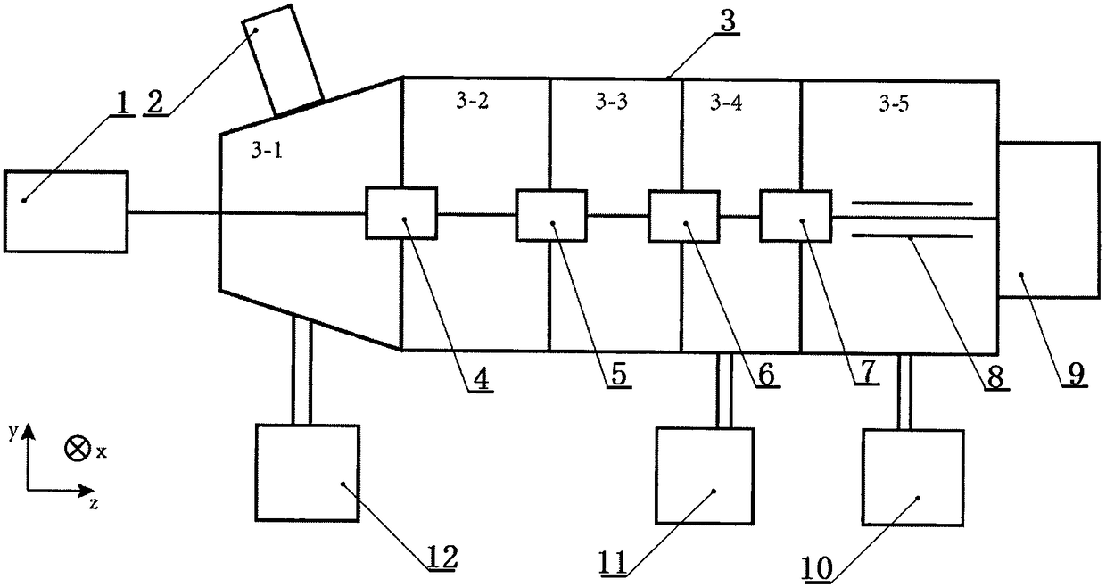
[0025] like figure 1It is a schematic diagram of the present invention, xyz is a three-dimensional space coordinate system, mainly including a laser (1), a droplet injector (2), a vacuum chamber (3), an ion beamer I (4), and an ion beamer II (5) , ion beamer III (6), ion beamer IV (7), quadrupole rod (8), detector (9), vacuum pump group I (10), vacuum pump group II (11), vacuum pump group III ( 12) and an ionization device, the vacuum chamber (3) has a starting end and an end, and in the vacuum chamber (3), there are a sample injection chamber (3-1) and a drift chamber 1 (3-2) sequentially from the starting end to the end ), drift chamber II (3-3), buffer chamber (3-4) and collision chamber (3-5), the sample injection chamber (3-1), buffer chamber (3-4) and collision chamber (3 -5) Vacuum pump group III (12), vacuum pump group II (11) and vacuum pump group I (10) are respectively connected; the ion buncher I (4), ion buncher II (5), ion buncher Device III (6), ion beamer IV ...


PUM

PropertyMeasurementUnit
thicknessaaaaaaaaaa

Abstract

The present invention relate to the field of spectrochemistry and discloses a testing device for free radical photoproduct. The testing device includes lasers, droplet ejector, vacuum chamber, ion buncher I, ion buncher II, Ion buncher III, Ion buncher IV, quadrupole bar, Vacuum pump set I, vacuum pump set II and vacuum pump set III, the method of reservoir resonance is adopted to generate and eject liquid droplets, the direction of vibration of the actuator is perpendicular to the direction in which the droplets are ejected, which can form droplets with much smaller size than the inner diameter of the droplet ejection port, and there is no special requirement for the polarity of the solvent, there is no need to apply high voltage during working and the applicable sample type is plural. Byadding a cushion cavity in the vacuum cavity, loss of ion beam in the vacuum cavity can be reduced as much as possible. The special designed ion buncher can be used for ion introduction, trapping andejection operation respectively, which effectively reduces the volume of the device and the pumping speed of the vacuum pump group.

Description

technical field [0001] The invention relates to the field of spectrochemistry, in particular to a free radical photoproduct testing device which has a special sample solution atomization method and can test photoreaction products of many kinds of free radicals. Background technique [0002] Devices for studying photoreaction products such as molecules or free radicals usually study the ion beam current of the molecule to be measured in a vacuum environment, and usually need to make the solution containing the sample to be tested atomized and then enter the vacuum environment. The first defect of the prior art: existing Some devices in the technology use the electrospray method to atomize the solution containing the sample to be tested, which has certain requirements for the solvent in the solution, that is, it must be a polar solution, and a high voltage must be applied to the liquid when the electrospray is working, which limits The type of sample that the electrospray meth...

Claims


Application Information

Patent Timeline
Patent Type & Authority Applications(China)
IPC IPC(8): H01J49/00G01N21/76
CPCH01J49/004G01N21/76
Inventor 张向平方蓉赵永建
Owner JINHUA VOCATIONAL TECH COLLEGE
Why Eureka
Try Eureka