magnetic assembly
A technology of magnetic components and windings, applied in electrical components, magnetic cores/yokes, inductors with magnetic cores, etc., which can solve the problem of high working voltage of magnetic components, harsh working environment, and difficulty in taking into account reliability and power density, etc. problem, to achieve the effect of uniform electric field strength, high reliability, and reducing the risk of partial discharge phenomenon
- Summary
- Abstract
- Description
- Claims
- Application Information
AI Technical Summary
Problems solved by technology
Method used
Image

Examples
Embodiment approach 1
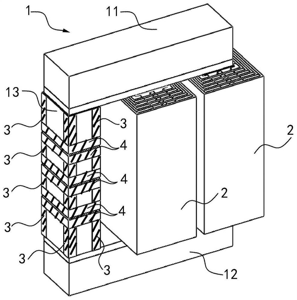
[0039] see figure 1 , figure 1 It is a three-dimensional structure schematic diagram of the first embodiment of the magnetic assembly of the present invention. Such as figure 1 As shown, the differential mode reactor of the present invention includes a magnetic core 1 and a winding 2. The magnetic core 1 includes an upper cover plate 11, a lower cover plate 12, and three windings arranged between the upper cover plate 11 and the lower cover plate 12. The winding post 13 is arranged around the winding post 13 . Of course, the number of winding posts 13 is not limited to three, and can be appropriately increased or decreased as required.
[0040] The winding post 13 is in the shape of a quadrangular prism, and has four longitudinal ribs parallel to each other along the longitudinal direction (direction of the centerline of the prism). The upper cover plate 11 , the lower cover plate 12 and the winding post 13 can be made of silicon steel sheets stacked, or made of ferrite, e...
Embodiment approach 2
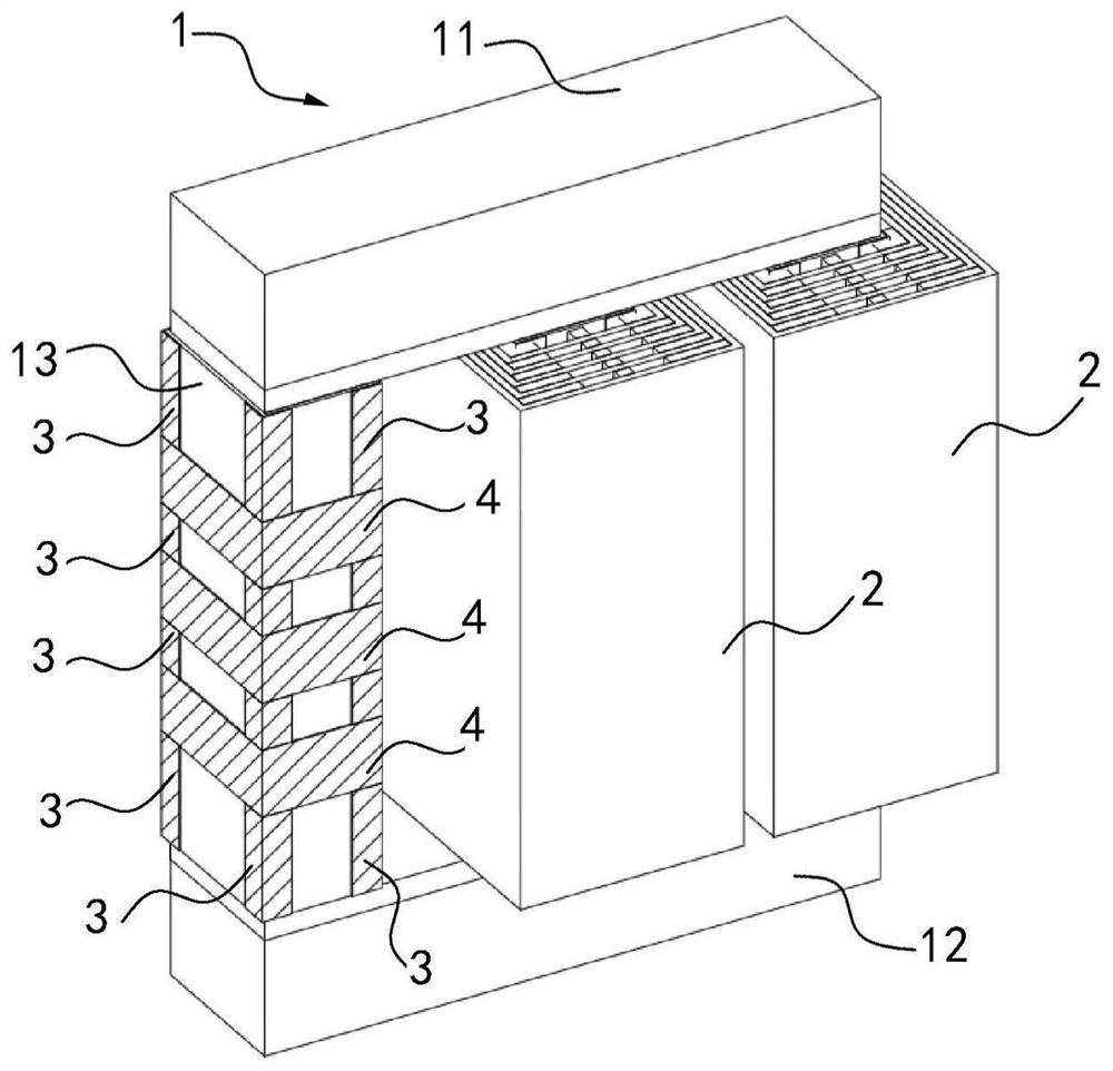
[0048] see figure 2 , figure 2 It is a three-dimensional structure schematic diagram of the second embodiment of the magnetic assembly of the present invention. The second embodiment of the magnetic assembly differs from the first embodiment only in that:
[0049] At least one first air gap is opened on the winding post 13, and a transverse edge is formed on the winding post 13 to define the first air gap position, and the side of each winding post 13 is covered with a first air gap corresponding to the position of the winding 2. Two semiconducting strips 4, and the second semiconducting strip 4 covers the first air gap. That is to say, the second semiconducting strip 4 is attached to the side of the winding post 13 and covers one surface of the two transverse edges defining the first air gap, thereby covering the first air gap; figure 1 In that way, one second semiconducting strip 4 is pasted on each horizontal edge separately, so the manufacturing process of the magneti...
Embodiment approach 3
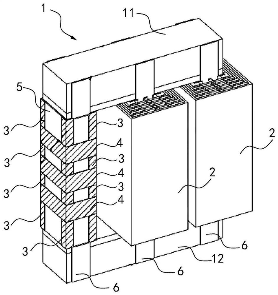
[0052] see image 3 , image 3 It is a three-dimensional structure diagram of the third embodiment of the magnetic assembly of the present invention. The third embodiment of the magnetic assembly is different from the second embodiment only in that:
[0053] The reactor of the third embodiment also includes an insulating cylinder 5 sleeved outside the winding post 13 , the cross-sectional shape of the insulating cylinder 5 may be the same as that of the winding post 13 , and the winding 2 is located outside the insulating cylinder 5 , in this case, the first semiconducting component and the second semiconducting component can be correspondingly arranged on the insulating cylinder 5 (see image 3 ), compared with directly disposing the semi-conductive component on the winding post, the heat dissipation performance of the winding post can be improved.
[0054] Of course, the present invention is not limited thereto. In the case where the insulating cylinder 5 is arranged outs...
PUM
 Abstract
Description
Claims
Application Information
 - R&D
- Intellectual Property
- Life Sciences
- Materials
- Tech Scout
- Unparalleled Data Quality
- Higher Quality Content
- 60% Fewer Hallucinations
Browse by: Latest US Patents, China's latest patents, Technical Efficacy Thesaurus, Application Domain, Technology Topic, Popular Technical Reports.
© 2025 PatSnap. All rights reserved.Legal|Privacy policy|Modern Slavery Act Transparency Statement|Sitemap|About US| Contact US: help@patsnap.com