
Dynamic design method of high-speed double-rolling bearing electric spindle rotor system

A rolling bearing and system dynamic technology, applied in computer-aided design, design optimization/simulation, calculation, etc., can solve the problem of not being able to obtain the corresponding relationship between the dynamic characteristics of the rotor system of the electric spindle and the bearing configuration mode, reducing the accuracy of the dynamic design of the electric spindle, and inability to Objectively reflect the dynamic behavior of high-speed motorized spindle rotors and other issues

Active Publication Date: 2018-12-11
SOUTHEAST UNIV
View PDF3 Cites 1 Cited by
  • Summary
  • Abstract
  • Description
  • Claims
  • Application Information

AI Technical Summary

Problems solved by technology

It should be noted that in the design methods of the high-speed double rolling bearing electric spindle rotor system that have been formed at home and abroad, the commonly used modeling methods: (1) Simplify the double rolling bearing into a spring element that only includes radial stiffness. Taking into account the angular stiffness of the bearing, the corresponding relationship between the dynamic characteristics of the rotor system of the electric spindle and the bearing configuration cannot be obtained. Therefore, the calculation results cannot objectively reflect the real rotor dynamic behavior of the high-speed electric spindle, which in turn greatly reduces the accuracy of the dynamic design of the electric spindle. sex

Method used


Image

  • Dynamic design method of high-speed double-rolling bearing electric spindle rotor system
  • Dynamic design method of high-speed double-rolling bearing electric spindle rotor system
  • Dynamic design method of high-speed double-rolling bearing electric spindle rotor system

Examples


Embodiment Construction

[0123] The method for dynamic design of the rotor system of the high-speed double rolling bearing electric spindle of the present invention will be further described in detail below in conjunction with an embodiment (51000rpm high-speed grinding electric spindle).

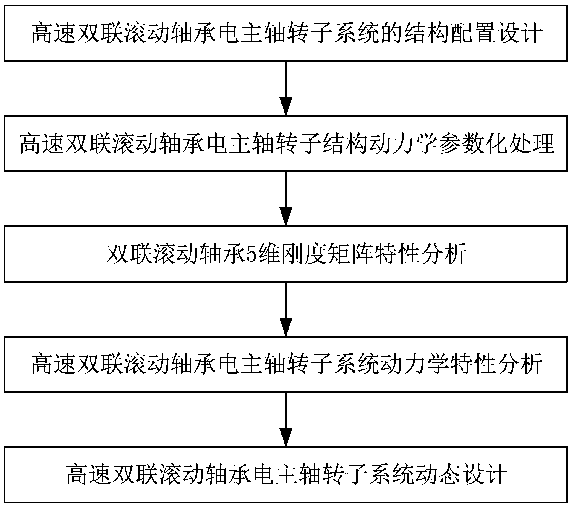
[0124] figure 1 The specific content of the dynamic design method of the high-speed double rolling bearing electric spindle rotor system of the present invention is given, including the following steps:

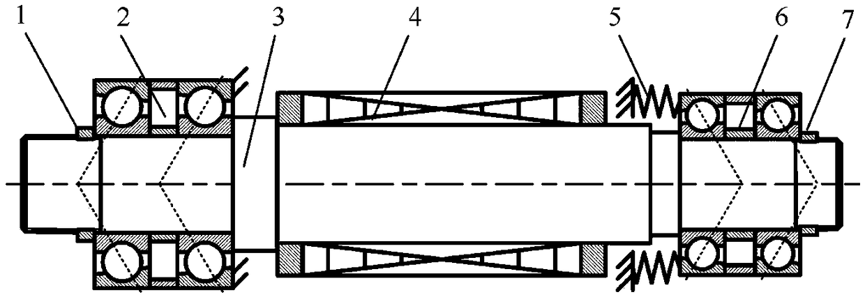
[0125] Step 1: According to the use requirements of the electric spindle: the working speed is 51000rpm, the static stiffness of the shaft end is greater than 10N / μm, complete the structural configuration design of the high-speed double rolling bearing electric spindle rotor system, such as figure 2 As shown: the main shaft rotor 3 is supported on two sets of double-connected rolling bearings, and the front bearing 2 and the rear bearing 6 are arranged in series. The motor rotor 4 is installed on the main shaft ...


PUM


Abstract

The invention provides a dynamic design method of a high-speed double-rolling bearing electric spindle rotor system. The method comprises the following steps: 1, designing the structure configurationof the high-speed double-rolling bearing electric spindle rotor system; 2, carrying out parameterize processing of the structure dynamics of the high-speed double-coupling roll bearing motor spindle rotor; 3, analyzing the characteristics of the 5-dimensional stiffness matrix of the double-coupling roll bearing; 4, analyzing the dynamics characteristic of a high-speed double-rolling bearing electric spindle rotor system; 5, performing dynamic design of a high-speed double-rolling bear electric spindle rotor system. Through adoption of the dynamic design method of the high-speed double-couplingrolling bearing electric spindle rotor system provided by the invention, the dynamic design precision of the electric spindle can be greatly improved, the design period can be shortened, and an effective method is provided for the design of the high-speed electric spindle.

Description

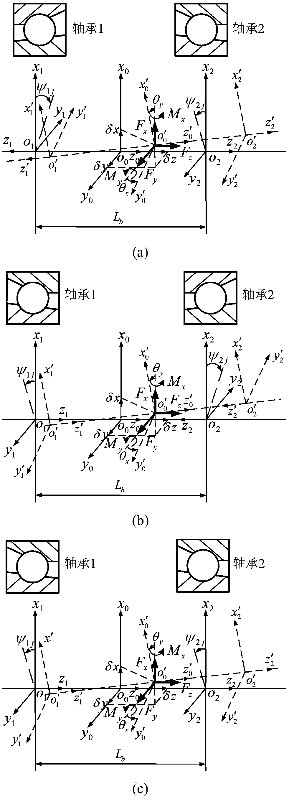
technical field [0001] The invention relates to a dynamic design method for a high-speed double-connected rolling bearing electric spindle rotor system, which belongs to the field of high-speed cutting machine tool spindle unit design. Background technique [0002] In order to improve the radial and axial rigidity of the electric spindle, the double rolling bearing replaces the single row rolling bearing and is widely used in the electric spindle of the high-speed machining machine tool. Duplex rolling bearings are usually arranged in three ways: face-to-face, back-to-back and tandem. The bearing configuration directly affects the angular stiffness of the duplex rolling bearing, and then affects the dynamic characteristics of the electric spindle rotor system. Therefore, in the design stage, in addition to determining the parameters such as the specification of the main shaft, the specification of the bearing, the support position and the preload, it is also necessary to de...

Claims


Application Information

Patent Timeline
IPC IPC(8): G06F17/50
CPCG06F30/17G06F30/20G06F2119/06
Inventor 蒋书运林圣业
Owner SOUTHEAST UNIV
Learn More