
Dynamic Design Method for Ball Screw Feed System of High Speed ​​Machine Tool

A feed system and dynamic design technology, applied in computer-aided design, calculation, geometric CAD, etc., can solve the problems of large errors in natural frequency analysis and harmonic response results, inability to objectively reflect the dynamic characteristics of machine tool feed systems, and long development cycles. , to achieve the effect of shortening the design cycle and improving the accuracy of dynamic design

Active Publication Date: 2020-01-10
SOUTHEAST UNIV
View PDF3 Cites 0 Cited by
  • Summary
  • Abstract
  • Description
  • Claims
  • Application Information

AI Technical Summary

Problems solved by technology

This kind of cyclic design process based on test means not only brings long development cycle and high cost, but also cannot identify the main factors affecting the dynamic characteristics of the feed system
[0004] The ball screw pair is the weak link of the feed system. In the dynamic design process of the traditional machine tool structure, the ball screw pair is usually simplified as a rigid connection, which cannot objectively reflect the dynamic characteristics of the machine tool feed system. The error of the natural frequency analysis and harmonic response results Larger, cannot meet the design requirements of the machine tool feed system

Method used


Image

  • Dynamic Design Method for Ball Screw Feed System of High Speed ​​Machine Tool
  • Dynamic Design Method for Ball Screw Feed System of High Speed ​​Machine Tool
  • Dynamic Design Method for Ball Screw Feed System of High Speed ​​Machine Tool

Examples


Embodiment Construction

[0057]In the following, an embodiment (3MK2332 internal grinding machine workpiece ball screw feed system) will be used to further describe the dynamic design method of the ball screw driven high-speed machine tool feed system of the present invention in detail.

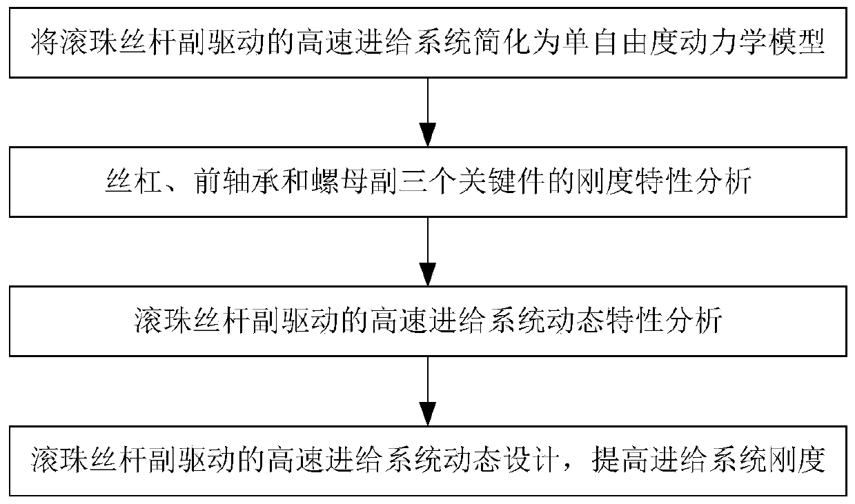
[0058] figure 1 The specific content of the dynamic design method of the high-speed machine tool feed system driven by the ball screw pair of the present invention is provided, including the following steps:

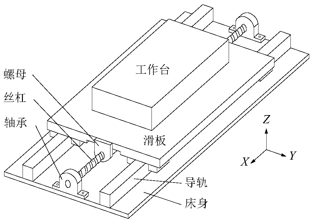
[0059] Step 1: The structure of the high-speed machine tool feed system driven by the ball screw pair is as follows figure 2 As shown: the lead screw is supported on the front and rear bearings, the servo motor is connected with the front end of the lead screw through a coupling, the nut is installed on the lead screw, and is located between the front and rear bearings, the workbench is fixedly connected above the nut, and the two The sides are supported by guide rails with sliders. The relevant parameters o...


PUM


Abstract

The invention provides a dynamic design method for a high-speed machine tool ball screw feeding system. The method comprises the following steps that: S1: simplifying a high-speed machine feeding system driven by a ball screw pair into a single-degree-of-freedom kinetic model; S2: carrying out the rigidity characteristic analysis of three key components including a lead screw, a front bearing anda nut pair; S3: analyzing the dynamic characteristics of the high-speed machine feeding system driven by the ball screw pair; and S4: dynamically designing the high-speed machine feeding system drivenby the ball screw pair, and improving the rigidity of the feeding system. By use of the dynamic design method for the high-speed machine feeding system driven by the ball screw pair, an effective means is provided for the dynamic characteristic analysis and the dynamic design of the high-speed machine feeding system driven by the ball screw pair, meanwhile, the dynamic design accuracy of the category of high-speed machine feeding systems is greatly improved, and a design period is shortened.

Description

technical field [0001] The invention relates to a dynamic design method of a feed system driven by a ball screw pair of a high-speed machine tool, belonging to the field of design of a feed system of a high-speed cutting machine tool. Background technique [0002] The high-speed machine tool feed system driven by the ball screw pair is composed of screw, bearing, nut, worktable and guide rail. As an important part of high-speed cutting machine tools, the dynamic characteristics of the feed system directly determine the positioning accuracy and machining accuracy of the machine tool. With the continuous increase of the machine tool speed, the cutting excitation causes the axial local resonance of the high-speed machine tool feed system, which sometimes occurs in high-speed machining machine tools. In engineering practice, once such resonance occurs, the cutting precision of the machine tool will be completely lost. Therefore, it is of great engineering value to study the dy...

Claims


Application Information

Patent Timeline
Patent Type & Authority Patents(China)
IPC IPC(8): G06F30/17
CPCG06F30/17G06F2119/06
Inventor 蒋书运林圣业
Owner SOUTHEAST UNIV
Learn More