Constant volume experiment device capable of simulating injection and atomization processes in isotropic and anisotropic turbulent flow fields

An experimental device and isotropic technology, applied in the field of constant volume experimental devices, can solve the problems of difficult control of turbulence scale, complicated fan structure design, increased design burden and processing difficulty, etc.

Inactive Publication Date: 2018-12-11
BEIJING JIAOTONG UNIV
View PDF5 Cites 2 Cited by
  • Summary
  • Abstract
  • Description
  • Claims
  • Application Information

AI Technical Summary

Problems solved by technology

In the constant-volume experimental device where the fan rotates to create turbulent flow, the turbulent flow is essentially an ordered swirling flow rather than a real disordered turbulent flow. The intensity of this turbulent flow is achieved by changing the structure of the fan and the rotation speed of the fan. However, the scale of turbulent flow is difficult to control; at the same time, the structural design of the fan is a complicated task, which adds a huge design burden and Processing difficulty

Method used


Image

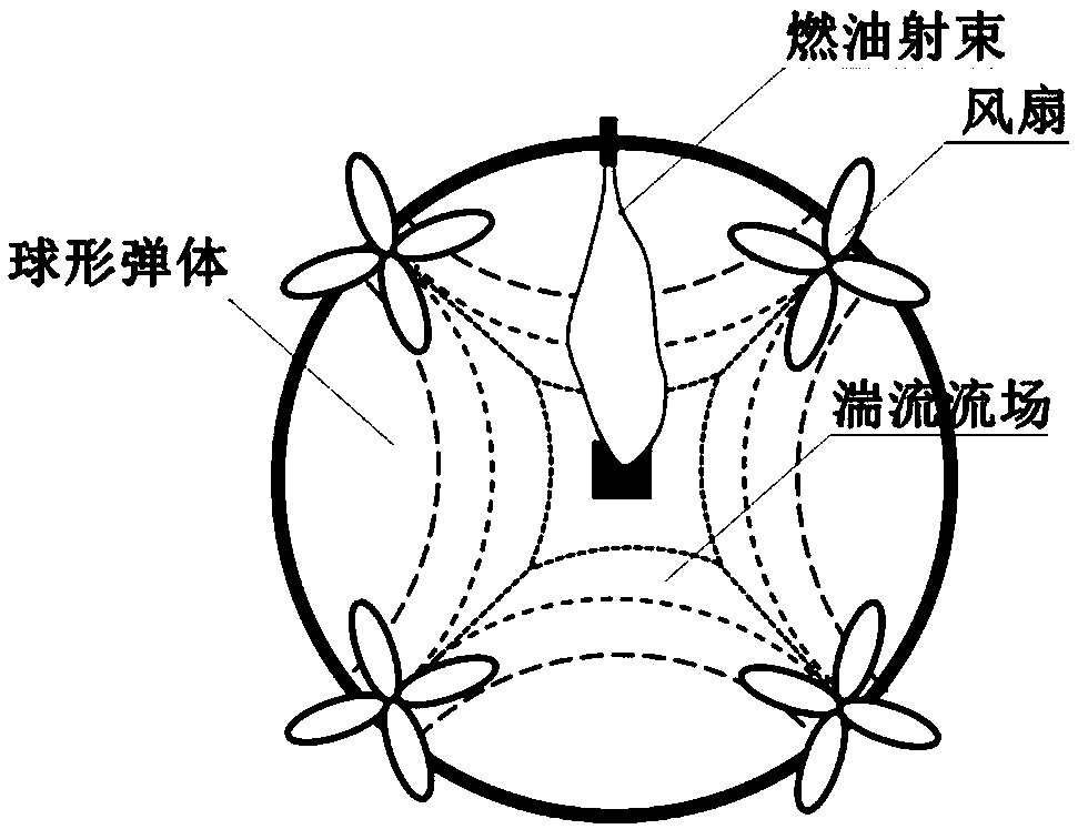
  • Constant volume experiment device capable of simulating injection and atomization processes in isotropic and anisotropic turbulent flow fields
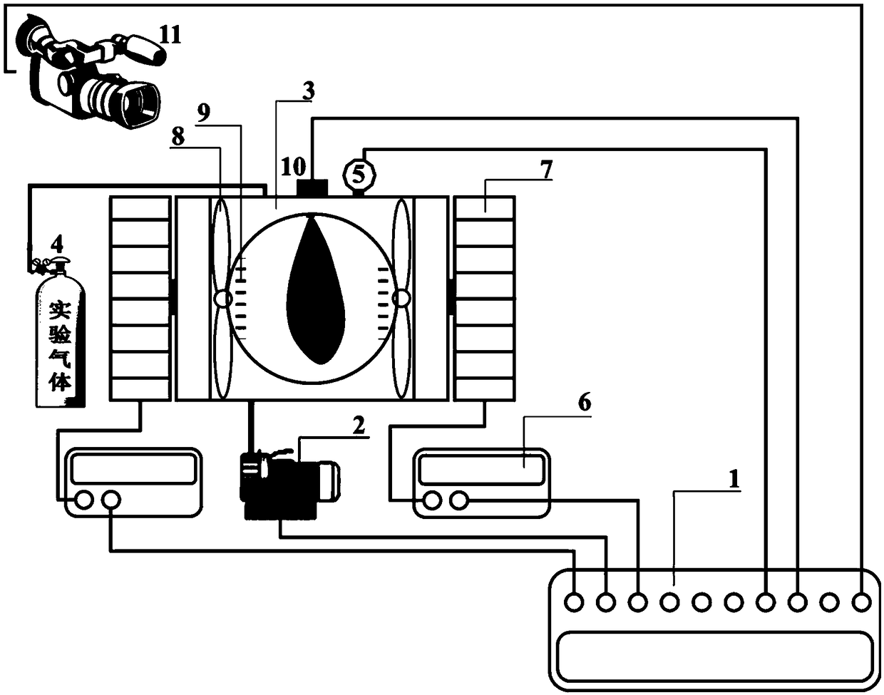
  • Constant volume experiment device capable of simulating injection and atomization processes in isotropic and anisotropic turbulent flow fields
  • Constant volume experiment device capable of simulating injection and atomization processes in isotropic and anisotropic turbulent flow fields

Examples


Embodiment Construction

[0023] Embodiments of the invention are described in detail below, examples of which are illustrated in the accompanying drawings. The embodiments described below by referring to the figures are exemplary only for explaining the present invention and should not be construed as limiting the present invention.

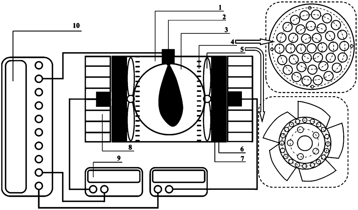
[0024] First, please refer to figure 2 , the structure of the constant volume experimental device for the study of the spray and atomization process in the isotropic turbulent flow field of a preferred embodiment of the present invention will be described in detail.

[0025] Specifically, the constant volume experimental device includes a cylindrical cavity 1, a fuel injector 2, an optical observation window 3, a porous orifice plate 4, an axial fan 5, a magnetic coupling 6, and a seal for the cylindrical cavity. End cover 7, rotating motor 8, frequency converter 9, electronic control unit 10. In this embodiment, the interior of the cylindrical cavity 1 is a cylindric...


PUM


Abstract

The invention provides a constant volume experiment device capable of simulating injection and atomization processes in isotropic and anisotropic turbulent flow fields. The experiment device comprisesa cylindrical cavity, an axial flow fan blade device, a porous orifice plate, a rotation motor, a frequency converter, a magnetic coupling, a fuel injector and an optical observation window, whereinthe diameter-length ratio of the cylindrical cavity is not less than 35%; the diameter of the axial flow fan blade device is between 80% and 100% of the inner diameter of the cylindrical cavity; the porous orifice plate converts a rotational flow formed by the axial flow fan blade device into a jet flow beam; the rotation motor and the frequency converter are used for controlling the rotation of the axial flow fan blade device; the magnetic coupling realizes the transmission between the axial flow fan blade device and the rotation motor through a non-contact magnetic force so as to avoid a leakage problem during an experiment; the fuel injector is installed in the center position of a cylindrical cavity bus; and the diameter of the optical observation window is not less than 65% of the inner diameter of the cylindrical cavity. When the experiment device is used to carry out turbulent jet and an atomization experiment, an experiment under an isotropic turbulence can be achieved, the experiment under a single mainstream turbulence can be realized, and the experiments under various complex anisotropic turbulences can also be realized.

Description

technical field [0001] The invention designs a constant volume experimental device, in particular to a constant volume experimental device capable of simulating the spraying and atomization process in an isotropic and anisotropic turbulent flow field. Background technique [0002] For vehicle and ship engines, the combustion performance is directly determined by the gas mixing quality, which is closely related to the fuel injection and atomization process in the engine cylinder. Therefore, basic research on fuel injection and atomization processes is essential Improving the economics and emissions of engine operation will be critical. In the cylinder of a car and ship engine, due to the action of multiple factors such as piston movement and intake air flow, the fuel injection and atomization processes all occur in a turbulent environment. Therefore, only by fully understanding the injection and atomization process of fuel in a turbulent environment, and deeply understanding...

Claims


Application Information

Patent Timeline
IPC IPC(8): G01M15/00
Inventor 孙作宇
Owner BEIJING JIAOTONG UNIV
Why Eureka
Try Eureka