
Locking device and unlocking method for mobile phone card slot

A mobile phone card and lock technology, applied in the field of information security, can solve the problems of secondary sales of mobile phones, leakage of information about the owner, and achieve the effect of simple structure and protection of personal information security.

Inactive Publication Date: 2018-12-07
CHENGDU IDING IND PROD DESIGN
View PDF0 Cites 0 Cited by
  • Summary
  • Abstract
  • Description
  • Claims
  • Application Information

AI Technical Summary

Problems solved by technology

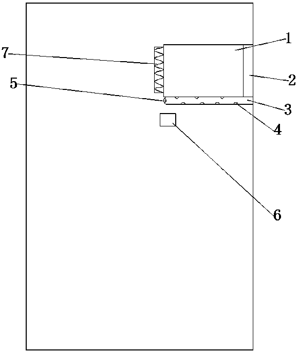
[0004] The purpose of the present invention is to provide a locking device and unlocking method for the card slot of a mobile phone in view of the above problems, which mainly solves the problem that the SIM card can be easily taken out after the mobile phone is stolen; it also solves the problem that the mobile phone is stolen. The problem of secondary sales; also solved the problem of the owner's information being leaked

Method used


Image

  • Locking device and unlocking method for mobile phone card slot
  • Locking device and unlocking method for mobile phone card slot
  • Locking device and unlocking method for mobile phone card slot

Examples


Embodiment 1

[0041] A locking device for a mobile phone card slot, such as figure 1 and figure 2 As shown, it includes card slot 1, card tray 2, slot 3 and card removal needle 9. The SIM card is placed in the card tray 2 and inserted into the card slot 1 together with the card tray 2. The slot 3 is located beside the card slot 1. It is used to insert the card removal needle 9 to make the card holder 2 pop out. An electromagnet 7 is arranged at the bottom of the card slot 1 for fixing the card holder 2 in the card slot 1. A control device is arranged between the slot 3 and the electromagnet 7. device 6, the controller 6 is respectively connected to the slot 3 and the electromagnet 7, an inductor 4 is installed in the slot 3, and there is a protruding structure 10 on the card taking needle 9, and the protruding structure 10 and the in the slot 3 Sensor 4 corresponds.

[0042] When the card removal needle 9 is inserted into the slot 3, the raised structure 10 on the card removal needle 9 w...

Embodiment 2

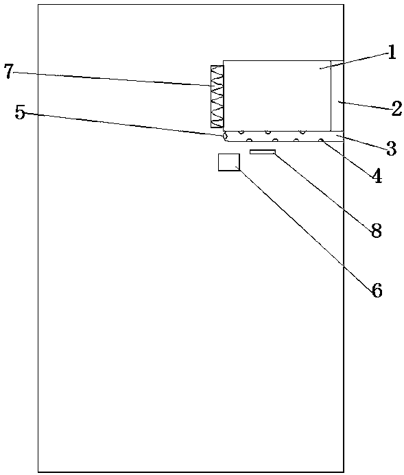
[0046] Embodiment 2 is similar to embodiment 1, and its difference is, as image 3 As shown, embodiment 2 also includes a determiner 8, which is located between the controller 6 and the slot 3 and is connected to the sensor 4 on the controller 6 and the slot 3 respectively, for identifying the slot 3 The sensor 4 that is activated on the vehicle will send the identified information to the controller 6.

[0047] In this embodiment, the judging device 8 will be initialized by software when it is used for the first time, and the activation number and sequence of the sensors 4 will be set during the initialization process. After the card taking pin 9 is inserted into the slot, the corresponding sensors will be activated 4. After the judging device 8 identifies correctly, it sends the identification information to the controller 6, and the controller 6 controls the electromagnet 7 to power off, and unlocks the card slot 1. Otherwise, the electromagnet 7 continues to be powered on, ...

Embodiment 3

[0051] Embodiment 3 is similar to Embodiment 2, and the difference is that the judger 8 can also be provided with statically activated sensors 4 and dynamically activated sensors 4, that is, some of the sensors 4 are activated in a fixed number and order, and some of the sensors are activated in a fixed number and order. The number and order of the sensors 4 are randomly specified by the software before unlocking the card slot 1 each time; for example, activating 6 sensors 4 through software settings can unlock the card slot 1, and the first 4 sensors 4 are activated in a fixed order , the last two sensors 4 are randomly designated by the software; the user applies to unlock the card slot 1 through the software, and the software will immediately randomly designate two sensors 4 that need to be activated, and display the identifier corresponding to the designated sensor 4 on the mobile phone Above, after the user inserts the card removal needle 9, first activates four fixed sens...


PUM


Abstract

The invention discloses a locking device and an unlocking method for a mobile phone card slot. The locking device comprises the card slot, a card tray, an insertion slot and a card picking pin, wherein a SIM card is placed in the card tray and inserted into the card slot together with the card tray; and the insertion slot is formed by the side of the card slot, and is used for inserting the card picking pin to eject the card tray. The locking device is characterized in that: an electromagnet is arranged at the bottom part of the card slot, and is used for fixing the card tray inside the card slot, a controller is arranged between the insertion slot and the controller, the controller is connected with the insertion slot and the electromagnet respectively and is used for controlling power-on / off of the electromagnet; a plurality of sensors are arranged inside the insertion slot, and are used for transmitting sensed information to the controller; a judging device is further arranged between the insertion slot and the controller, and the judging device is connected with the controller and the sensors in the insertion slot respectively; and the card picking pin is provided with a plurality of convex structures for activating the sensors. By adopting the locking device and the unlocking method, the SIM card cannot be taken out after a mobile phone is stolen, thus the mobile phone cannot be resold, and the personal information of a mobile phone user is protected, thus the information stored in the SIM card cannot be stolen easily.

Description

technical field [0001] The invention relates to the field of information security, in particular to a locking device and unlocking method for a card slot of a mobile phone. Background technique [0002] As a communication tool, the mobile phone has become an indispensable device in life. With the continuous popularization of mobile phones, the number of stolen and lost mobile phones is also increasing. When the mobile phone is stolen, the thief usually takes out the SIM card and puts the The mobile phone is sold after restoring the factory settings, which damages the information security of the owner to a certain extent, and may be used by criminals. Therefore, protecting the SIM card of the mobile phone from being taken out after the mobile phone is stolen, so that the mobile phone cannot be re-sold is protection An important technology for machine owner information security. [0003] In the prior art, most of the methods to prevent the SIM card from being taken out are to...

Claims


Application Information

Patent Timeline
Patent Type & Authority Applications(China)
IPC IPC(8): H04M1/02H04M1/725H01R43/26H01R13/639H01R13/633H01R12/71
CPCH01R12/714H01R13/633H01R13/639H01R43/26H01R2201/16H04M1/026H04M1/72403
Inventor 谭远良
Owner CHENGDU IDING IND PROD DESIGN
Learn More