Clock generation device based on phase-locked loop and standard ruler delay line and implementation method thereof

A technology of clock generation and implementation method, applied in the direction of automatic power control, electrical components, etc., to achieve the effects of high stability, light weight and small size

Pending Publication Date: 2018-12-07
HARBIN INST OF TECH
View PDF4 Cites 1 Cited by
  • Summary
  • Abstract
  • Description
  • Claims
  • Application Information

AI Technical Summary

Problems solved by technology

[0007] The purpose of the present invention is to solve the problem that the existing technology can only realize the conversion from frequency to frequency, and provides a clock generation device based on a phase-locked loop and a standard scale delay line and its implementation method

Method used


Image

  • Clock generation device based on phase-locked loop and standard ruler delay line and implementation method thereof
  • Clock generation device based on phase-locked loop and standard ruler delay line and implementation method thereof
  • Clock generation device based on phase-locked loop and standard ruler delay line and implementation method thereof

Examples


specific Embodiment approach 1

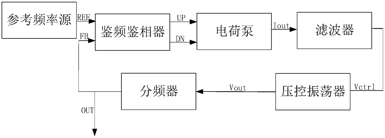
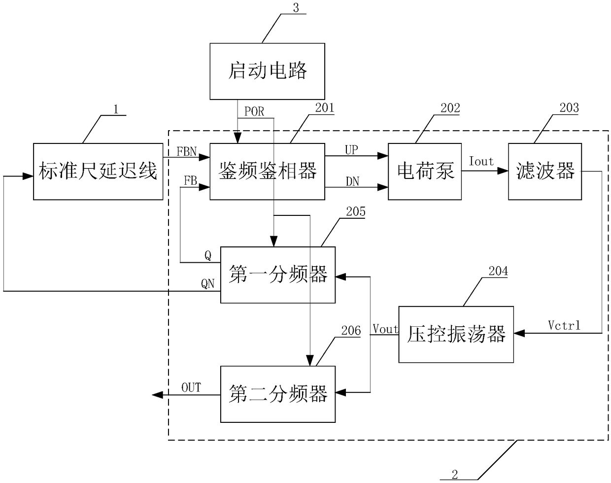
[0034] Specific implementation mode one: the following combination figure 2 Describe this embodiment mode, the clock generation device based on phase-locked loop and standard scale delay line described in this embodiment mode, this clock generation device comprises standard scale delay line 1 and phase-locked loop 2; Phase-locked loop 2 comprises frequency discriminator phase detector 201, charge pump 202, filter 203, voltage controlled oscillator 204, first frequency divider 205 and second frequency divider 206;

[0035] The UP output end and the DN output end of the frequency discrimination phase detector 201 are respectively connected to the UP input end and the DN input end of the charge pump 202, and the current output end I of the charge pump 202 out Connect the current input terminal of the filter 203, the output terminal V of the filter 203 ctrl Connect the input end of the voltage-controlled oscillator 204, the clock signal output end Vout of the voltage-controlled ...

specific Embodiment approach 2

[0036] Specific implementation mode two: the following combination figure 2 Describe this embodiment mode, this embodiment mode will further explain Embodiment 1, the clock generating device also includes a start-up circuit 3;

[0037] The reset output terminal of the start-up circuit 3 is simultaneously connected to the reset input terminal of the frequency and phase detector 201 , the reset input terminal of the first frequency divider 205 and the reset input terminal of the second frequency divider 206 .

[0038] In this embodiment, the initial states of the frequency and phase detector 201 , the first frequency divider 205 and the second frequency divider 206 are very important, and the startup circuit 3 is used to ensure that the initial states are correct.

specific Embodiment approach 3

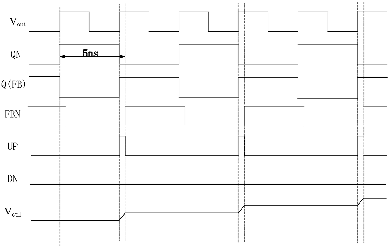
[0039] Embodiment 3: In this embodiment, Embodiment 1 is further described. The first frequency divider 205 is a frequency divider in a loop, and the Q output terminal and the QN output terminal of the first frequency divider 205 are symmetrical.

[0040] In this embodiment, the first frequency divider 205 is used as a frequency divider in the loop, and a two-way frequency divider is used. The two outputs Q and QN must have a high degree of symmetry, that is, the QN signal is not simply in the Q signal. Then connect an inverter to get it. In the present invention, the two-frequency divider is composed of eight three-input NAND gates plus an inverter.


PUM


Abstract

The present invention provides a clock generation device based on phase-locked loop and standard ruler delay line and an implementation method thereof, belonging to the technical field of a clock. Theproblem is solved that conversion from frequency to frequency can be only achieved in the prior art. A UP output end and a DN output end of a phase frequency detector are respectively connected witha UP input end and a DN input end of a charge pump, the current output end of the charge pump is connected with a current input end of a filter, an output end of the filter is connected with an inputend of a voltage-controlled oscillator, a clock signal output end of the voltage-controlled oscillator is connected with a clock signal input end of a first frequency divider and a clock signal inputend of a second frequency divider, Q output end of the first frequency divider is connected with an FB input end of the phase frequency detector, the QN output end of the first frequency divider is connected with the input end of the standard ruler delay line, the output end of the standard ruler delay line is connected with the FBN input end of the phase frequency detector, and the output of thesecond frequency divider is taken as output of a clock generation device. The clock generation device based on phase-locked loop and standard ruler delay line and the implementation method thereof areused for clocking metering.

Description

technical field [0001] The invention relates to a clock generator based on the principle of a phase-locked loop and a standard scale delay line and an implementation method thereof, belonging to the technical field of clocks. Background technique [0002] With the development of the times, the accuracy of measurement is becoming more and more important in military, aerospace and communication. The accuracy of measurement needs the support of reference frequency sources. The most widely used reference sources are crystal oscillators and atomic clocks. [0003] A crystal oscillator is an electronic circuit that utilizes the piezoelectric effect of a crystal material to generate mechanical resonance to obtain a frequency electrical signal. If measures such as temperature compensation are not taken in the crystal oscillator, the frequency stability of the crystal oscillator is only 10 -5 Order of magnitude, after adding the temperature compensation circuit, the frequency stabil...

Claims


Application Information

Patent Timeline
Patent Type & Authority Applications(China)
IPC IPC(8): H03L7/099H03L7/18
CPCH03L7/099H03L7/18
Inventor 王永生赵罕付方发韩维佳
Owner HARBIN INST OF TECH
Why Eureka
Try Eureka