
Holographic waveguide displaying device

A display device, holographic waveguide technology, applied in the direction of optical components, optics, instruments, etc., can solve the problems of unsatisfactory field of view expansion effect, complex grating exposure process, high refractive index modulation degree, etc., and achieve simple and compact optical structure, preparation and processing Easy, low-cost effect

Inactive Publication Date: 2018-12-07
SOUTHEAST UNIV
View PDF4 Cites 9 Cited by
  • Summary
  • Abstract
  • Description
  • Claims
  • Application Information

AI Technical Summary

Problems solved by technology

In addition, Wu Yishi et al. from Shanghai Jiaotong University simulated a composite holographic grating structure to expand the diffraction angle bandwidth of the grating. The composite holographic grating package has five different grating periods and grating inclination angles. However, this scheme requires the preparation of the The refractive index modulation degree of the holographic recording material of the grating is very high, and the grating exposure process is very complicated
[0005] In the above several schemes, the input and output optical coupling elements are all reflective volume holographic gratings, and the field of view expansion effect is not ideal, and the design and process are relatively complicated.

Method used


Image

  • Holographic waveguide displaying device
  • Holographic waveguide displaying device

Examples


Embodiment 1

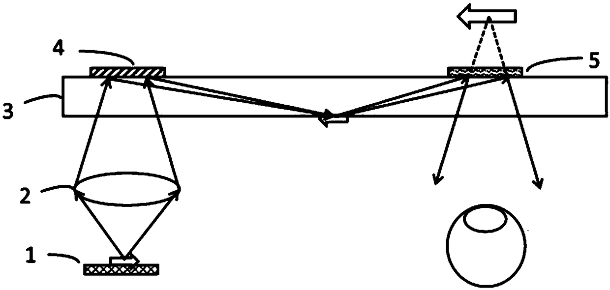
[0027] Such as figure 1 As shown, the multi-angle collimated microdisplay 1 emits a light beam with image information to the lens group 2. The light beam is refracted by the lens group to reach the holographic waveguide, and first passes through the flat waveguide 3 to reach the reflective volume holographic grating 4 located in the input area of ​​the waveguide. The light beam It is diffracted by the holographic grating 4 into the waveguide 3, propagates in the waveguide 3 in the form of total reflection, and forms an inverted real image during the propagation of the waveguide, and finally reaches the output area of ​​the slab waveguide 3, and diffracts into the waveguide 3 through the reflective volume holographic lens 5. The human eye forms an upright enlarged virtual image in front of the human eye.

[0028] The lens group 2 is a doublet lens (objective lens), the diameter of the lens is 50 mm, the focal length is 40 mm, and the field angle is 20 degrees; the reflective vo...

Embodiment 2

[0031] Such as figure 1 As shown, the multi-angle collimated microdisplay 1 emits a light beam with image information to the collimator lens group 2, and the light beam is refracted by the collimator lens group 2 to reach the holographic waveguide, and first passes through the slab waveguide 3 to reach the reflective body located in the input area of ​​the waveguide Holographic lens 4, the light beam is diffracted by the holographic lens 4 into the waveguide 3, propagates in the waveguide 3 in the form of total reflection, and forms an inverted real image during the waveguide propagation process, and finally reaches the output area of ​​the slab waveguide 3. The holographic lens 5 diffracts into the human eye, forming an upright enlarged virtual image in front of the human eye.

[0032] Lens group 2 is a collimating lens group with a focal length of 30 mm; reflective volume holographic lens 4 is a doublet lens (objective lens) with a lens diameter of 50 mm, a focal length of 8...

Embodiment 3

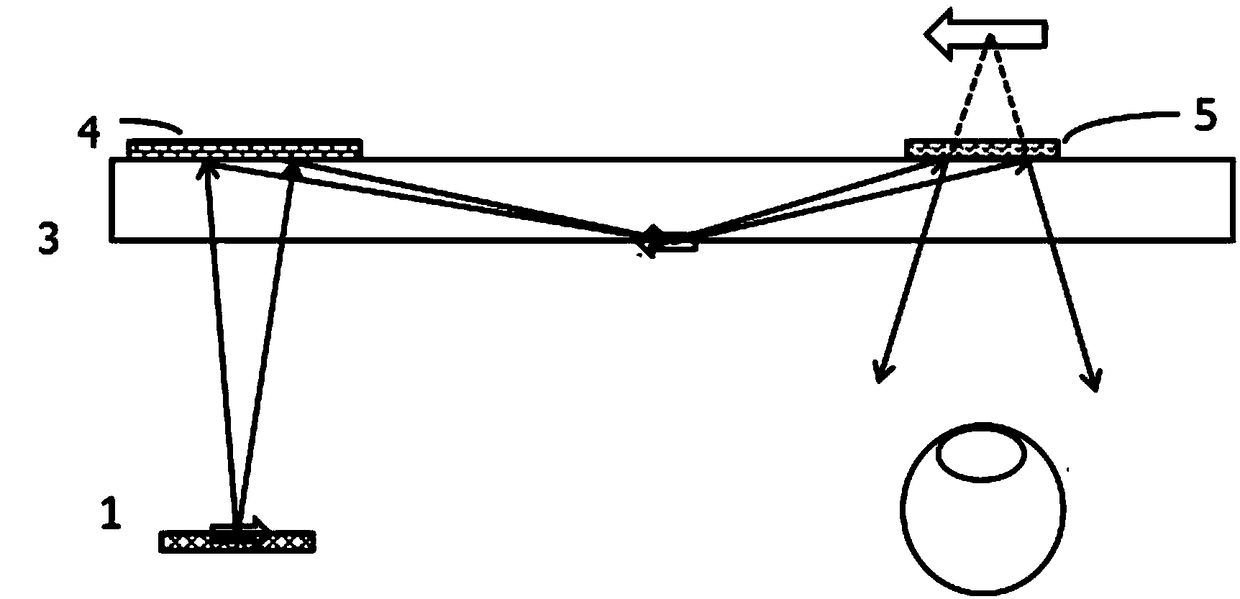
[0035] Such as figure 2As shown, the multi-angle collimated microdisplay 1 emits a light beam with image information to the slab waveguide 3, first passes through the slab waveguide 3 and reaches the reflective volume holographic lens 4 located in the input area of ​​the waveguide, and the light beam is diffracted by the holographic lens 4 and enters the waveguide 3 , propagating in the waveguide 3 in the form of total reflection, and form an inverted real image during the propagation process of the waveguide, and finally reach the output area of ​​the slab waveguide 3, diffract into the human eye through the reflective volume holographic lens 5, and form a positive image in front of the human eye Standing magnified virtual image.

[0036] The reflective volume holographic lens 4 is recorded in the photopolymer, the reference light angle is 45 degrees, and the object light angle is 0 degree; the reflective volume holographic lens 4 is a lens group, the diameter of the lens gr...


PUM

PropertyMeasurementUnit
Thicknessaaaaaaaaaa
Thicknessaaaaaaaaaa
Lens diameteraaaaaaaaaa

Abstract

The invention discloses a holographic waveguide displaying device which comprises the components of a multi-angle calibrating micro display device, a lens set, a planar waveguide, an in-coupling holographic optical diffraction element and an out-coupling holographic optical diffraction element. The in-coupling holographic optical diffraction element and the out-coupling holographic optical diffraction element form a telescope optical system. The picture of the micro display device is arranged at a certain position to human eyes and is projected to an upright amplified virtual image, thereby realizing a large visual field effect. Furthermore, through a holographic waveguide structure, the optical path of the traditional coaxial telescope optical system can be turned for entering the human eyes, thereby forming an off-axis optical system which can be used for a penetrating type headworn displaying. The holographic waveguide displaying device is based on a traditional telescope optical system principle; and through the holographic waveguide structure, a coaxial telescope system is turned to the off-axis optical system which is suitable for the penetrating type headworn displaying, thereby settling problems of small visual field and small exit pupil in a traditional holographic waveguide display device. The holographic waveguide displaying device has advantages of simple and compact optical structure, easy operation in preparing and processing, low cost, small weight, etc.

Description

technical field [0001] The invention belongs to the technical field of head-mounted displays, and in particular relates to a holographic waveguide display device. Background technique [0002] In recent years, many researchers have been studying a holographic waveguide structure. The input and output optical coupling elements of this structure are reflective volume holographic gratings with mirror symmetry. . The display principle of this structure is that the image emitted by the microdisplay is firstly collimated by the collimating optical system, then diffracted into the holographic waveguide through the in-coupling holographic grating, and finally coupled into the human eye through the output holographic grating. [0003] After research, the field of view of the holographic waveguide display configuration is mainly determined by the collimation optical system and the angular wavelength bandwidth of the volume holographic grating. However, the angle selectivity and wave...

Claims


Application Information

Patent Timeline
IPC IPC(8): G02B27/01
CPCG02B27/0172G02B2027/0174
Inventor 张宇宁沈忠文刘奡翁一士李晓华
Owner SOUTHEAST UNIV
Learn More