
Method for quickly assembling and adjusting axisymmetric telescope with image plane as datum

An assembly and adjustment method and telescope technology, applied in telescopes, optics, instruments, etc., can solve the problems of high working environment requirements, sensitive environmental factors, and high tool precision, and achieve the effects of easy portability and transportation, simple overall structure, and good visualization

Active Publication Date: 2018-12-07
NAT ASTRONOMICAL OBSERVATORIES CHINESE ACAD OF SCI
View PDF4 Cites 9 Cited by
  • Summary
  • Abstract
  • Description
  • Claims
  • Application Information

AI Technical Summary

Problems solved by technology

Common self-collimation detection and assembly methods (Gao Tianyuan, Research on the structural design and assembly method of sub-aperture splicing imaging system [D], Changchun: Changchun University of Science and Technology, 2012, 53-58) require high-precision plane mirrors and matching references The light source and detector have high detection and assembly accuracy, but they are sensitive to environmental factors, and the required tools have high precision and high requirements for the working environment
The method of inspection and assembly using tools such as micro-collimation telescopes and high-precision auxiliary tooling (Li Depei. Adjustment and inspection of astronomical optical telescopes [J]. Optical Technology, 1998, 24(3): 27-31), Inspection and assembly The accuracy is high, but the workload is heavy, the required tooling is various, and a large number of personnel are required to cooperate

Method used


Image

  • Method for quickly assembling and adjusting axisymmetric telescope with image plane as datum
  • Method for quickly assembling and adjusting axisymmetric telescope with image plane as datum
  • Method for quickly assembling and adjusting axisymmetric telescope with image plane as datum

Examples


Embodiment Construction

[0026] Examples of the present invention are described below. But following embodiment only limits to explain the present invention, and protection scope of the present invention should comprise the whole content of claim, and promptly can realize the whole content of claim of the present invention to those skilled in the art through following embodiment.

[0027] The invention fully utilizes the characteristics of the high-precision rotary mechanism and the axisymmetric telescope, and has simple process, easy realization and high precision.

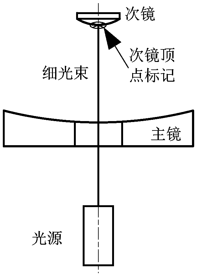
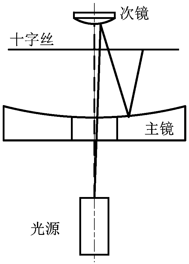
[0028] The optical adjustment tool used in the present invention includes parts such as high-precision rotary structure, observation window, high-precision tilt adjustment mechanism and low divergence angle laser, and the specific structure is as follows figure 1 shown. The set-up tool is attached near the installation image plane via a precision-fit adapter. Utilizing the rotary characteristics of the high-precision rotary mechanism, ...


PUM


Abstract

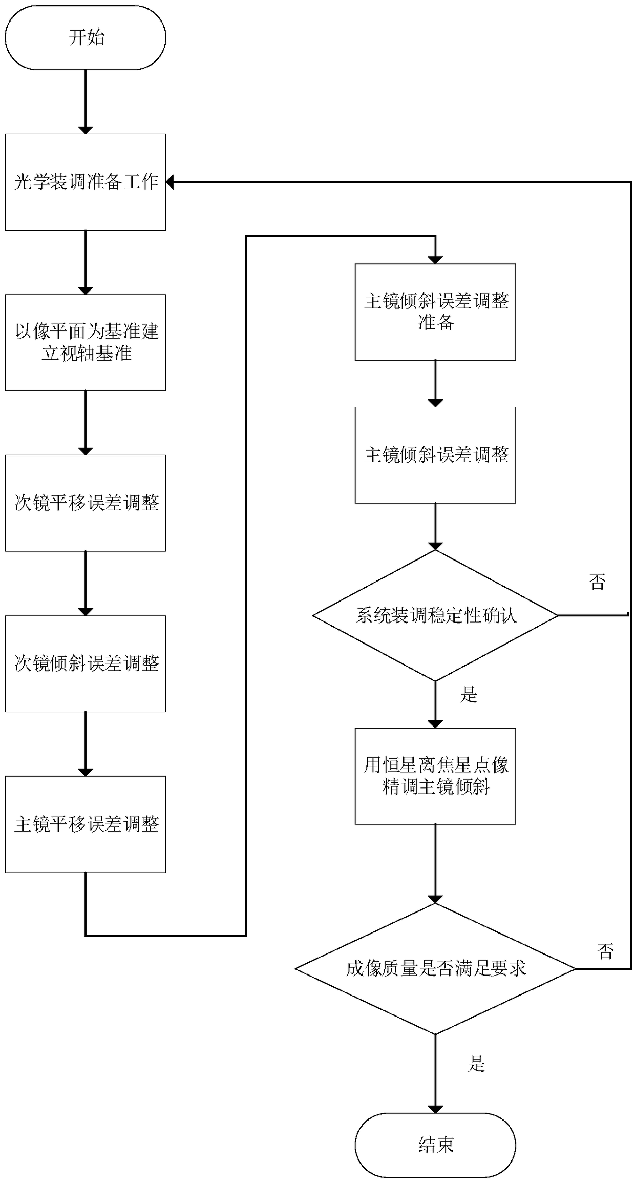
A method for quickly assembling and adjusting an axisymmetric telescope with the image plane as a datum provided by the invention comprises the following main steps: (1) a visual axis datum which is perpendicular to the image plane and passes through the center of the image plane is established by using an outgoing beam; (2) the secondary mirror is assembled and adjusted based on the fact that thenormal vector of the vertex of the secondary mirror coincides with the optical axis; and (3) a cross wire is drawn between the primary and secondary mirrors of the telescope, and the primary mirror is assembled and adjusted based on the spin symmetry of an axisymmetric optical system. The tools used for assembly and adjustment have the following characteristics: (1) a laser is used to produce anoutgoing beam as a reference beam; (2) the outgoing beam can rotate with high precision; and (3) high-precision tilt adjustment can be carried out on the outgoing beam around a point on the axis of rotation, and the axis where the outgoing beam is located passes through the tilt adjustment center. The method of the invention is suitable for quickly assembling and adjusting an axisymmetric telescope, and can also be used for installing a transmission optical module. The assembling and adjusting tools are simple and convenient to use.

Description

technical field [0001] The invention belongs to the technical field of optical telescope detection and assembly, and relates to a technical method for optical telescope assembly and adjustment. Specifically, certain tools and methods are used to quickly complete the low-precision optical assembly and adjustment work of the telescope. Background technique [0002] At present, in the field of optical telescope detection and assembly technology, the method of adjusting optical telescopes is to first complete the design and processing of a telescope, and only after completing the assembly and adjustment according to a certain technical method can it work normally. The main task of telescope assembly and adjustment is to ensure that each optical component is in the space position required by the design. Conventional assembly and adjustment methods require micro-collimation telescopes, pentaprisms, micro-adjustment platforms, etc., as well as a large number of tooling. The worklo...

Claims


Application Information

Patent Timeline
Patent Type & Authority Applications(China)
IPC IPC(8): G02B23/10G02B23/16G02B27/62
CPCG02B23/10G02B23/16G02B27/62
Inventor 张晓明陈颖为王建峰李陶然曾显群葛亮田健峰邱鹏侯志刚方立国
Owner NAT ASTRONOMICAL OBSERVATORIES CHINESE ACAD OF SCI
Learn More