Reflector support and fixing method

A mirror support and fixing method technology, applied in installation, optics, instruments, etc., can solve the problems of forced displacement unloading ability and thermal deformation unloading ability, large flexibility of support structure, poor seismic performance, etc., to reduce dynamic response. Amplitude, reduced structural weight, good stability

Active Publication Date: 2018-12-07
BEIJING RES INST OF SPATIAL MECHANICAL & ELECTRICAL TECH
View PDF8 Cites 1 Cited by
  • Summary
  • Abstract
  • Description
  • Claims
  • Application Information

AI Technical Summary

Problems solved by technology

[0004] Generally speaking, the higher the stiffness of the supporting structure of the mirror assembly, the higher the fundamental frequency under dynamic conditions, the smaller the stress response amplitude, and the safer the structure; Ability then becomes worse
The existing flexible support method is prone to structural damage under vibration conditions due to the large flexibility and low stiffness of the support structure and poor seismic performance.

Method used


Image

  • Reflector support and fixing method
  • Reflector support and fixing method
  • Reflector support and fixing method

Examples


Embodiment Construction

[0043] The specific implementation manners of the present invention will be described in further detail below in conjunction with the accompanying drawings and specific embodiments.

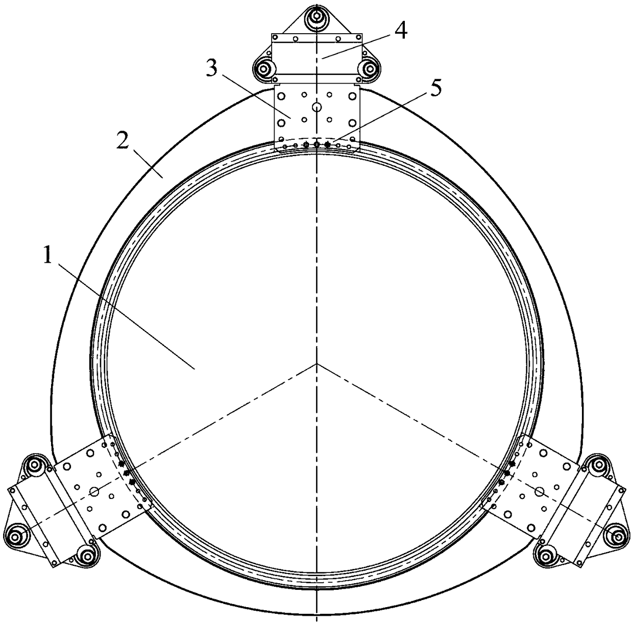
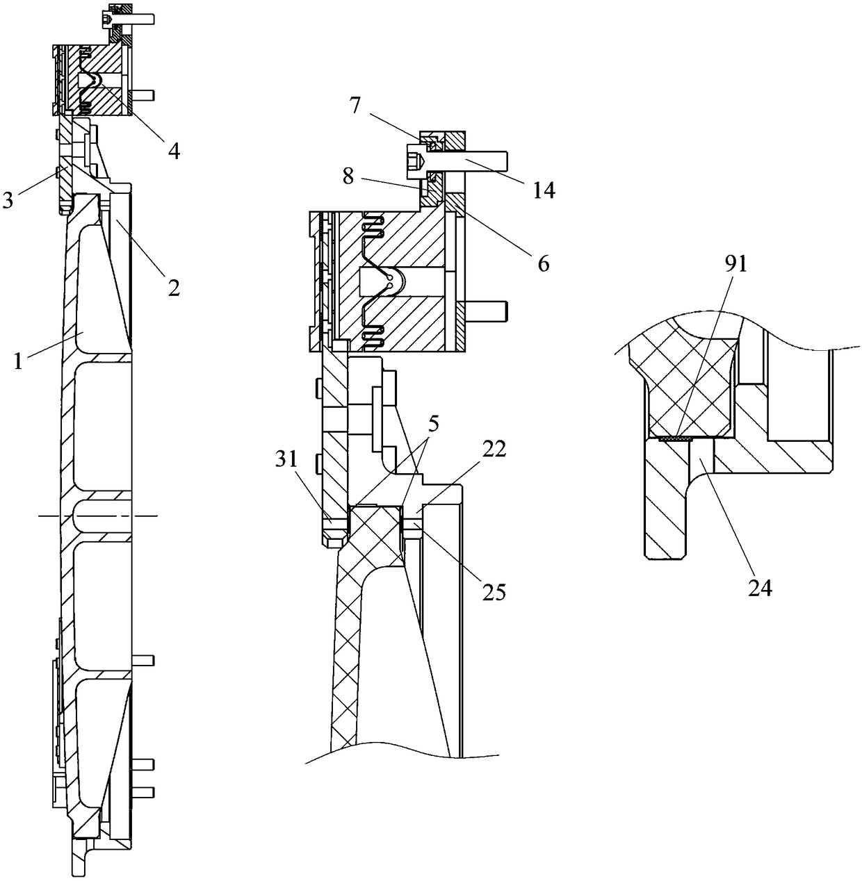
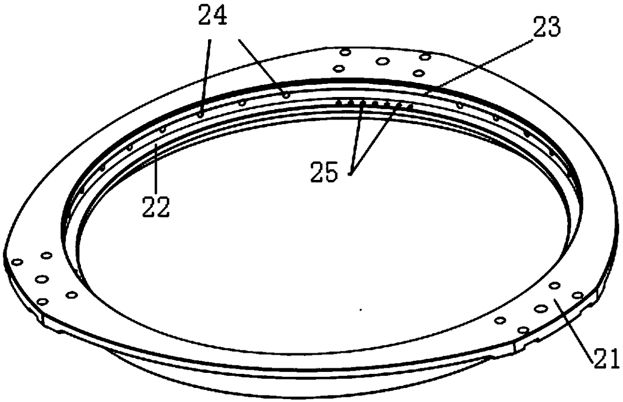
[0044] see figure 1 As shown, the embodiment of the present invention provides a reflector support and fixing device for connecting the reflector 1 with the lens body frame, especially suitable for reflectors with a diameter not greater than 400mm. Such as figure 1 and 2 As shown, in the embodiment of the present invention, the reflector 1 is a circular reflector, and the upper and lower sides of the periphery are respectively provided with a circle of concave ring belts. The supporting and fixing device includes a support frame 2, three pressing blocks 3, six A film 5, three flexible bearings 4 and three groups of flexible bearing fixing components, such as image 3 and 4 As shown, the support frame 2 is an annular frame, and three flanges 21 are evenly distributed on the periphery along the...


PUM


Abstract

The present invention provides a reflector support and fixing method, belonging to the technical field of space optical remote sensors. The method comprises the steps of: fixing the reflector on a holding frame module, and filling impedance glue to a flexible support and performing solidification for the flexible support, wherein the flexible support comprises a first connection portion and a second connection portion, the first connection portion is connected with the holding frame module, the second connection portion is connected with a lens main body frame, the first connection portion andthe second connection portion are in hinged connection through a first flexible hinge and a second flexible hinge which are orthogonally arranged, the rotation directions of the first flexible hingeand the second flexible hinge are perpendicular to the optical axis direction of the reflector, the first flexible hinge and the second flexible hinge are provided with a plurality of glue insertion grooves which are used for filling the impedance glue to allow the rotational tangential direction of the flexible hinges to have damping; and fixing and connecting the holding frame module and the lens main body frame through the flexible support through glue filling. The reflector support and fixing method achieves flexible support for the reflector and avoids damaging of the structure caused byvibration.

Description

technical field [0001] The invention relates to a method for supporting and fixing a reflecting mirror, which belongs to the technical field of space optical remote sensors. Background technique [0002] The supporting structure of the aerospace remote sensor mirror usually includes a metal bracket and at least three pressing blocks arranged on the bracket, the metal bracket is used to support the mirror, and the pressing blocks are used to fix the bracket with reflector. [0003] In aerospace remote sensors, small-aperture mirrors are generally supported by rigid, semi-flexible and flexible structures. Among them, the existing flexible support structure usually uses flexible elements to realize the flexible connection between the mirror and the frame, such as using a flexible pressing block to directly connect the mirror and the frame, or using a pressing block and a pad to be arranged between the mirror and the frame. The flexible connection between the mirror and the fr...

Claims


Application Information

Patent Timeline
Patent Type & Authority Applications(China)
IPC IPC(8): G02B7/182G02B7/192
CPCG02B7/182
Inventor 孙熠璇罗世魁陈芳高超刘子嘉白杰张凤芹伏瑞敏张孝弘
Owner BEIJING RES INST OF SPATIAL MECHANICAL & ELECTRICAL TECH
Why Eureka
Try Eureka