
Flexible electromagnetic ultrasonic guided wave sensor for tube, and detection method thereof

An electromagnetic ultrasonic and sensor technology, which is applied in the analysis of solids using sound waves/ultrasonic waves/infrasonic waves, material analysis using sound waves/ultrasonic waves/infrasonic waves, and instruments. It can solve the problems of large probe volume, complicated installation, and high installation surface requirements.

Active Publication Date: 2018-12-07
XI AN JIAOTONG UNIV
View PDF6 Cites 10 Cited by
  • Summary
  • Abstract
  • Description
  • Claims
  • Application Information

AI Technical Summary

Problems solved by technology

At present, there are mainly three methods for pipeline guided wave detection: one is the pipeline guided wave detection system using conventional piezoelectric probes, which belongs to contact ultrasonic detection, requires liquid couplant, has a large probe volume, and has high requirements for the surface of the detection object. It is more complex and the probe is limited by the diameter of the pipe; the other is the electromagnetic ultrasonic guided wave method using a patch-type magnetostrictive tape. The belt has high requirements on the installation surface, and the installation is more complicated; the third is the non-contact electromagnetic ultrasonic guided wave detection system, which can realize the guided wave detection under the condition that the probe is lifted off, and has very low requirements on the installation surface. The magnet or electromagnet of the structure provides a bias magnetic field, the probe is large in size, easily limited by the diameter of the pipe, and difficult to detect in a narrow space environment

Method used

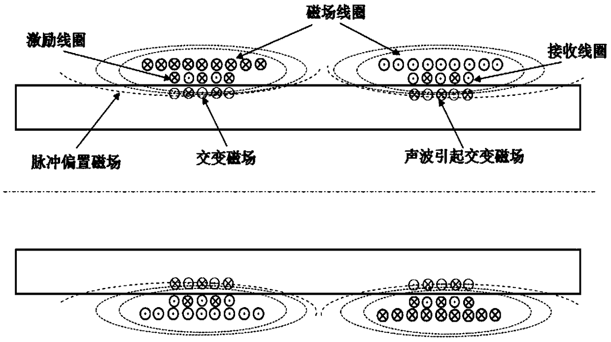

Image

  • Flexible electromagnetic ultrasonic guided wave sensor for tube, and detection method thereof
  • Flexible electromagnetic ultrasonic guided wave sensor for tube, and detection method thereof
  • Flexible electromagnetic ultrasonic guided wave sensor for tube, and detection method thereof

Examples


Embodiment Construction

[0018] The present invention will be described in further detail below in conjunction with the accompanying drawings and specific embodiments.

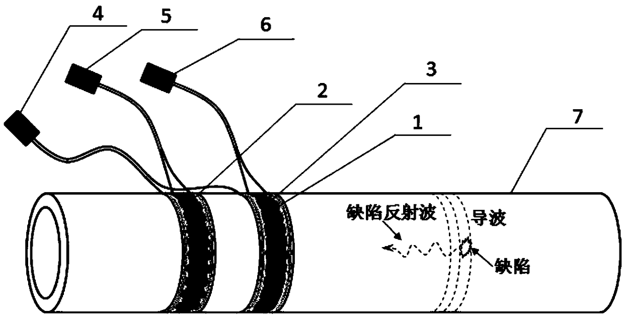
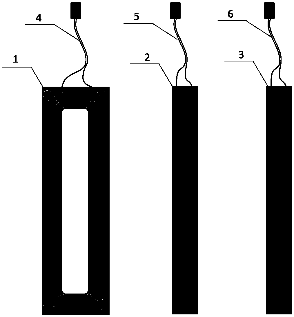
[0019] Such as figure 1 and figure 2 As shown, the flexible electromagnetic ultrasonic guided wave sensor of the present invention is composed of a pulse bias magnetic field coil 1, an electromagnetic ultrasonic excitation coil 2, an electromagnetic ultrasonic receiving coil 3, a flexible protective layer and three shielding wires 4, 5, 6; The ultrasonic excitation coil 2 and the electromagnetic ultrasonic receiving coil 3 are pasted directly below the two sides of the pulse bias magnetic field coil 1 respectively, and each of the three coils is connected to a shielded wire, and the other end of the shielded wire is connected to a two-core plug.

[0020] Such as figure 2 As shown, the pulse bias magnetic field coil 1 of the flexible electromagnetic ultrasonic guided wave sensor used in the present invention is a planar racetrack c...


PUM


Abstract

The invention provides a flexible electromagnetic ultrasonic guided wave sensor for a tube, and a detection method. The sensor comprises a runway type pulse bias magnetic field coil, a foldback type electromagnetic ultrasonic excitation coil, a foldback type electromagnetic ultrasonic receiving coil and a flexible protection layer; the electromagnetic ultrasonic excitation coil and the receiving coil are respectively stuck to the bottoms of two sides of the pulse bias magnetic field coil, the three coils are respectively connected with a shielded lead wire, and the other end of the shielded lead wire is connected with a two-pin plug; and the whole sensor is a flexible, flat and openable-closable structure. The detection method comprises the following steps: tying the sensor around the a detected pipeline, applying a rectangular pulse current to the bias magnetic field coil to generate a pulsed bias magnetic field, and applying a high-power radiofrequency current to the electromagneticultrasonic excitation coil to realize non-contact excitation and reception of ultrasonic guided waves. The sensor can be used for rapid detection of narrow space environments and pipelines with different diameters.

Description

technical field [0001] The invention relates to pipeline ultrasonic guided wave detection technology, in particular to a flexible electromagnetic ultrasonic guided wave sensor for pipes and a detection method, which can be used for long-distance and high-efficiency nondestructive detection of corrosion defects and cracks on pipe walls of different metal pipes. Background technique [0002] Pipelines are widely used in various important industrial fields. In some special environments, they are often accompanied by harsh working conditions such as high temperature, high pressure, and wear. During long-term operation, various defects such as corrosion and cracks are prone to occur on the pipe wall. These defects will It will cause major accidents such as pipeline cracking and material leakage in the pipeline. Therefore, non-destructive testing of pipelines is of great significance to ensure its safe operation and prevent accidents. Ultrasonic guided wave testing technology, as ...

Claims


Application Information

Patent Timeline
IPC IPC(8): G01N29/04G01N29/22
CPCG01N29/04G01N29/048G01N29/22
Inventor 裴翠祥刘天浩陈振茂
Owner XI AN JIAOTONG UNIV
Learn More