
Impact and rubbing experiment device of rotating stator

An experimental device, the technology of rotating the stator, applied in the direction of measuring device, testing of mechanical components, testing of machine/structural components, etc., to achieve full-featured results

Inactive Publication Date: 2018-12-07
NORTHEASTERN UNIV
View PDF2 Cites 19 Cited by
  • Summary
  • Abstract
  • Description
  • Claims
  • Application Information

AI Technical Summary

Problems solved by technology

[0005] In order to solve the above-mentioned problems in the prior art, the present invention provides a rubbing experimental device for rotor-stators, which solves the shortcomings of existing rubbing test benches, and is an experimental device for more realistically simulating the rubbing process of rotor-stators, which can be used for simulating and measuring leaves. The friction force magnitude and direction, blade dynamic stress and other data when the disk is rubbed at different speeds, different intrusions, sudden unbalance, and different casing coatings

Method used


Image

  • Impact and rubbing experiment device of rotating stator
  • Impact and rubbing experiment device of rotating stator
  • Impact and rubbing experiment device of rotating stator

Examples


Embodiment 1

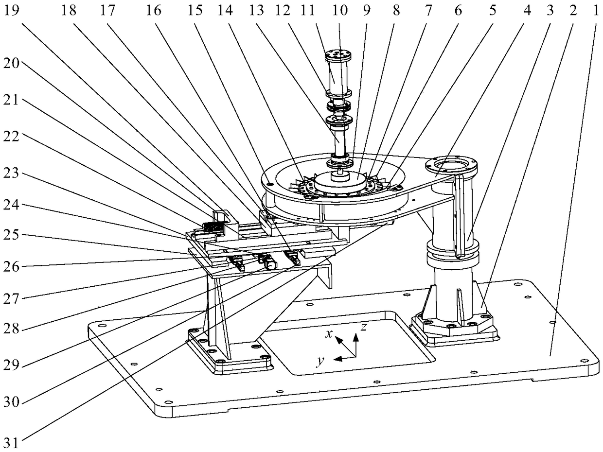
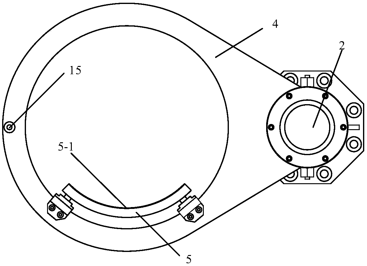
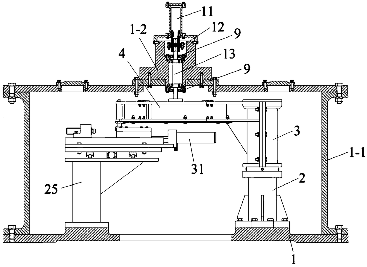
[0038] The rubbing test device of the rotor stator provided by the present invention includes a box base, a box body, a three-way load cell, a displacement characteristic sensor, a strain gauge, a rubbing support mechanism, a leaf disc balance mechanism, a main shaft transmission mechanism and a gap adjustment mechanism, wherein the rubbing support mechanism is fixed on one side above the box base, the rubbing support mechanism is provided with a support ring, and the support ring is used as a stator, the main shaft transmission mechanism is fixed above the box body, and the main shaft transmission mechanism is connected to the leaf disk balance mechanism. And provide power for the blisk balance mechanism, the blisk of the blisk balance mechanism is used as the rotor, the stator and the rotor are arranged correspondingly, the rotor is placed in the middle of the stator, that is, the blisk is placed in the ring of the support ring. There is a casing on the inner wall of the supp...

Embodiment 2

[0064] Experimental device provided by the present invention carries out test process and can adopt following operation to carry out:

[0065] 1. Preparation before the test:

[0066] The experimental device should pre-adjust the rubbing gap to 0 before the experiment, and adjust the intrusion through the gap adjustment mechanism. The negative pole of the power supply is connected to the blade, and the positive pole of the power supply is connected to the casing. The current signal generates a current signal when it is in contact (generating an intrusion), so the gap is adjusted to 1 μm when the current is just generated through the gap adjustment mechanism, and the gap is considered to be 0.

[0067] 2. Friction characteristics at different speeds

[0068] For the rubbing characteristics at different speeds, it is necessary to control the remaining variables to remain unchanged. Set a given amount of rubbing, such as 50 μm, and drive the main shaft to rotate through the air ...


PUM


Abstract

The invention relates to the impact and rubbing experiment device of a rotating stator. The device comprises a box seat, a box body, a three-dimensional force measurement sensor, an impact and rubbingsupport mechanism, a leaf disc balancing mechanism, a main shaft transmission mechanism and a gap adjusting mechanism. In the device, the gap adjusting mechanism is used to adjust a rotating stator gap so as to realize different impact and rubbing intrusion amounts. Through adopting the leaf disc balancing mechanism, when a rotor is rotated at a high speed, mass eccentricity is generated throughelectromagnetic control, a sudden unbalance amount is generated, and the rotor is rotated in an imbalance mode so as to generate impact and rubbing. Through changing a casing coating material in the impact and rubbing support mechanism, the impact and rubbing testing of different casing coating materials is realized. The experiment device analyzes the influence rules of different intrusion amounts, intrusion rates, different balance states, different coating materials and coating thicknesses and other parameters on an impact and rubbing force. And based on test data, an existing theory model is corrected.

Description

technical field [0001] The invention relates to a rubbing test device for a rotor stator, belonging to the technical field of blade fault test simulation devices. Background technique [0002] For rotating machinery, rotor-stator rubbing is a common failure that can easily cause mechanical failure. As a special case of rotor-stator rubbing: the rubbing between the blade and the casing, due to the high tangential velocity of the blade , The collision energy is large, and bending deformation is more likely to occur, which will lead to local damage to the blade, such as blade drop and high-cycle fatigue of the blade root. [0003] Most of the existing rubbing devices are single-pendulum rubbing devices, which do not match the actual rubbing situation; by adjusting the number of screws, point rubbing, partial rubbing and full-circle rubbing can be realized, which cannot be simulated well Real rubbing conditions; these experiments cannot accurately determine the amount of intrus...

Claims


Application Information

Patent Timeline
Patent Type & Authority Applications(China)
IPC IPC(8): G01M7/02G01M7/00G01M13/00
CPCG01M7/02G01M7/00G01M13/00
Inventor 马辉曹野
Owner NORTHEASTERN UNIV
Learn More