
Subglacial marine optical observation equipment

An observation equipment and marine technology, applied in the field of sub-ice ocean optical observation equipment, can solve the problems of difficulty in placing equipment under the ice and large errors in observation data, and achieve the effects of improved accuracy, small data errors, and avoiding scratches

Pending Publication Date: 2018-12-07
THIRD INST OF OCEANOGRAPHY STATE OCEANIC ADMINISTATION +1
View PDF0 Cites 5 Cited by
  • Summary
  • Abstract
  • Description
  • Claims
  • Application Information

AI Technical Summary

Problems solved by technology

[0003] The invention provides a device aimed at improving the problems of large errors in observation data and difficulty in placing equipment under the ice

Method used


Image

  • Subglacial marine optical observation equipment
  • Subglacial marine optical observation equipment
  • Subglacial marine optical observation equipment

Examples


Embodiment 1

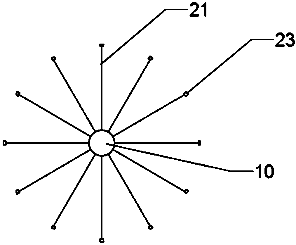
[0034] Embodiment 1, the present invention provides a sub-ice ocean optical observation device, comprising: a vertical pole 10, a plurality of measuring units 20, at least two symmetrically arranged support units 30, and a telescopic sleeve set on the vertical pole 10 barrel 40,

[0035] refer to Figure 1-3 As shown, the vertical rod 10 includes an observation end 11 and a fixed end 12 connected with the observation end 11; the fixed end 12 is used to fix the device on the ice, and the fixed end 12 is connected with a support Platform, the supporting platform is stably fixed on the ice surface to ensure the stability of the fixed end 12 .

[0036]A plurality of the measuring units 20 are equidistantly arranged on the observation end 11 of the vertical rod 10; each of the measuring units 20 includes a measuring bracket 21, a first spring 22 and a probe 23; the measuring bracket 21 One end of one end is hinged with the vertical rod 10, so that the measuring bracket 21 can for...

Embodiment 2

[0042] The implementation principle and technical effect of the device provided by the embodiment of the present invention are the same as those of Embodiment 1. For a brief description, reference may be made to the corresponding content in Embodiment 1 for the parts not mentioned in this embodiment.

[0043] The device obtained through the above design can basically meet the use of sub-ice ocean optical observation equipment, but in line with the purpose of further improving its function, the designer has made further improvements to the device.

[0044] refer to Figure 5 As shown, on the basis of the structure of Embodiment 1, the junction of each section of the telescopic sleeve 40 and the previous section of the sleeve is provided with a buckle 44 for when the telescopic sleeve 40 When unfolding and extending along the observation end 11, each segment of the sleeve is clamped and fixed with the previous segment of the sleeve to ensure that when the device is placed in sea...


PUM


Abstract

The invention provides subglacial marine optical observation equipment, which comprises a vertical bar, a plurality of measuring units, at least two symmetrically arranged support units and a telescopic sleeve sleeved on the vertical bar. The vertical bar comprises an observation end and a fixed end; the plurality of measuring units are arranged at the observation end of the vertical bar at an equal interval; each measuring unit includes a measuring support, a first spring and a probe; the support units are disposed at the fixed end of the vertical bar; each support unit includes a support rodand a second spring, and one end of the telescopic sleeve is fixed at one side of the fixed end far from the observation end; when the telescopic sleeve contracts, the measuring supports and the support rods are all in an open state; and when the telescopic sleeve extends along the observation end, the support units and the measuring units can be accommodated in the telescopic sleeve. According to the invention, the equipment is not affected by the flow of subglacial seawater, has small error of measured data and improved accuracy, and the protection of the telescopic sleeve also makes the equipment convenient to use and reduces damage.

Description

technical field [0001] The invention relates to the field of ocean underwater detection, in particular to a sub-ice ocean optical observation device. Background technique [0002] Since the late 1990s, the extent of sea ice has been decreasing at an accelerated rate, especially in summer, when open water is growing. The gradually increasing open water area can absorb a large amount of solar radiation and delay the freezing of sea ice in autumn and winter. The gradual thinning of sea ice allows more solar radiation to penetrate the sea ice and enter the ocean. On the one hand, it can provide sufficient photosynthesis for algae under the ice; on the other hand, seawater absorbs more solar radiation to accelerate seawater warming. In the context of accelerated melting of sea ice, understanding optical changes in the subglacial ocean will be of great interest. At present, most of the optical measurement equipment is based on the design of the laboratory. The general optical e...

Claims


Application Information

Patent Timeline
Patent Type & Authority Applications(China)
IPC IPC(8): G01C13/00
CPCG01C13/00
Inventor 王维波朱大勇王福利
Owner THIRD INST OF OCEANOGRAPHY STATE OCEANIC ADMINISTATION
Learn More