
Heat storage and drying system for timber and drying method thereof

A drying system and wood drying technology, which is applied in the field of wood drying, can solve the problems of high drying energy consumption, serious pollution of the environment, and low recovery and utilization rate of waste heat, and achieve energy saving, good condensation effect, and good heat storage effect.

Pending Publication Date: 2018-12-07
浙江泰昌新能源有限公司
View PDF11 Cites 2 Cited by
  • Summary
  • Abstract
  • Description
  • Claims
  • Application Information

AI Technical Summary

Problems solved by technology

[0002] At present, wood drying is a large energy-consuming household of wood processing enterprises, accounting for about 40% of the total energy consumption of wood products; 70% 14J is one of the main targets of energy saving and emission reduction in this industry; More than 80%, the main problems are: 1) Drying consumes a lot of energy. At present, coal-fired oil-fired boilers are mainly used, which seriously pollutes the environment
Enterprises must switch from coal to electricity or gas, or purchase the required hot water and steam from thermal power plants, so the energy costs of enterprises are getting higher and higher; 2) The heat loss of air intake and exhaust in the drying room is very large, and the recovery and utilization rate of waste heat Low

Method used


Image

  • Heat storage and drying system for timber and drying method thereof
  • Heat storage and drying system for timber and drying method thereof

Examples


Embodiment

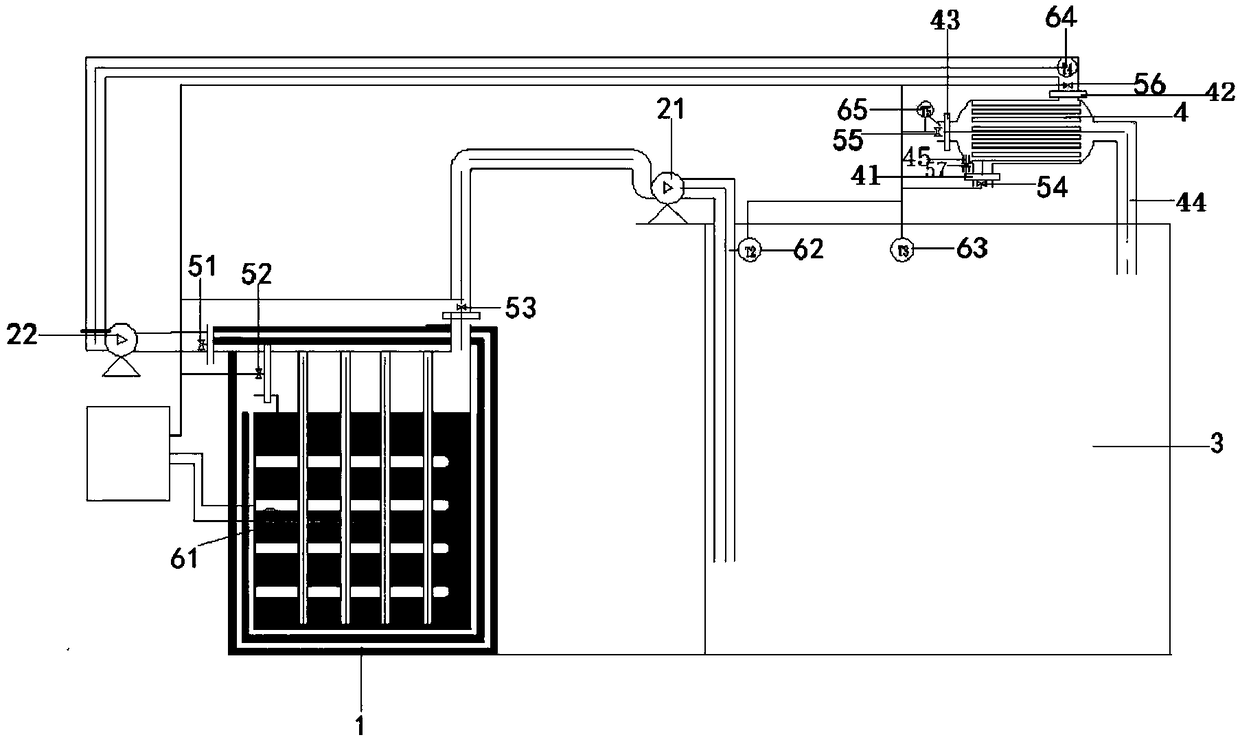
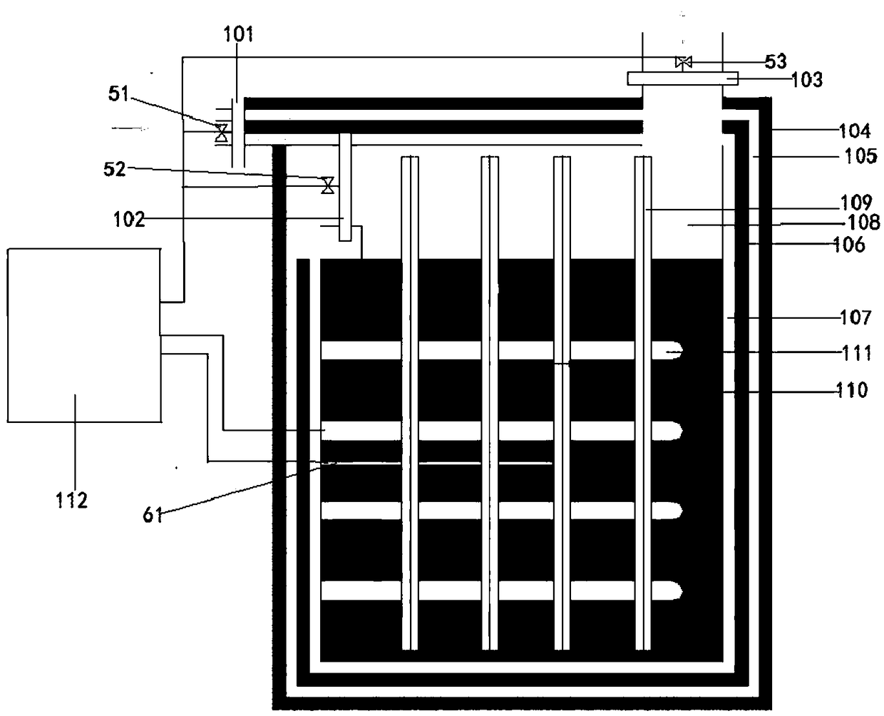
[0040] Such as figure 1 , figure 2As shown, the present invention provides a heat storage drying system for wood, the heat storage drying system includes: a heat storage drying device 1, a fan, a wood drying chamber 3, a condenser 4; the fan includes a fan one 22, a fan two 21; heat storage drying device 1, fan 2 21, wood drying chamber 3, condenser 4 and fan 1 21 are connected in turn through pipelines to form a cycle; condenser 4 includes condenser cold air inlet 41, condenser air outlet 2 42, Condenser air inlet one 44, condenser air outlet one 43, condenser condensed water outlet 45; Condenser air inlet one 44 links to each other with wood drying chamber 3; Air outlet three 103 links to each other with fan two 21; In the heat drying system, the condenser cold air inlet 41 is installed with valve four 54, the condenser condensate outlet 45 is installed with valve seven 57, and the condenser air outlet two 42 is installed with valve six 56; heat storage and drying Device ...


PUM

PropertyMeasurementUnit
Phase transition temperatureaaaaaaaaaa

Abstract

The invention relates to the wood drying industry, in particular to a heat storage and drying system for timber and a drying method thereof. The requirement of a timber enterprise for a drying processare met; the heat storage and drying system comprises a heat storage and drying device, a fan, a timber drying chamber and a condenser; the heat storage and drying system for the timber and the drying method thereof disclosed by the invention have the following advantages that a novel structure heat storage device is adopted; and a novel heat storage phase change material is adopted, a multi-airduct and a stepped phase change material heat preservation technology are adopted, a traditional heat preservation material is abandoned, and a novel heat exchange structure is adopted. Waste heat isrecycled, heat exhausted in the timber drying chamber through ventilation is subjected to heat cold air exchange through the condenser, the hot air is recycled and enters the heat storage device for utilization; and valley electricity is used for heat storage so that the production continuity can be guaranteed, meanwhile, energy is saved for the enterprise, and economic benefits are created.

Description

technical field [0001] The invention relates to the wood drying industry, in particular to a heat storage drying system for wood and a drying method thereof. Background technique [0002] At present, wood drying is a large energy-consuming household of wood processing enterprises, accounting for about 40% of the total energy consumption of wood products; 70% 14J is one of the main targets of energy saving and emission reduction in this industry; More than 80%, the main problems are: 1) Drying consumes a lot of energy. At present, coal-fired oil-fired boilers are mainly used, which seriously pollutes the environment. At the same time, the state has put forward restrictive goals for energy conservation and emission reduction. The hot water and steam required for thermal drying in enterprises have gradually begun to be prohibited from burning coal, and some areas have restricted biomass fuels. Enterprises must switch from coal to electricity or gas, or purchase the required ho...

Claims


Application Information

Patent Timeline
IPC IPC(8): F26B9/06F26B21/00F26B25/00F26B3/04
CPCF26B3/04F26B9/06F26B21/002F26B21/004F26B25/00F26B2210/16
Inventor 孙爱东梁忠胡宝建童敏张鹏飞
Owner 浙江泰昌新能源有限公司
Learn More