Method for lifting and releasing descending mechanism through intelligent winch device

A hoisting device, intelligent technology, applied in the direction of hoisting device, clockwork mechanism, fluid pressure actuating device, etc., can solve the problem that the movement cannot be guaranteed at one time, the lifting and lowering mechanism cannot move, and the buffer friction braking cannot be realized and other problems, to achieve the effect of improving the deceleration and braking effect, improving the working reliability and service life, and the effect of large braking torque

Active Publication Date: 2018-12-07
63921部队
View PDF8 Cites 8 Cited by
  • Summary
  • Abstract
  • Description
  • Claims
  • Application Information

AI Technical Summary

Problems solved by technology

Therefore, if the control method of the prior art is used to make the brake brake, there are the following hidden dangers: (1) if the deceleration adopts electric brake deceleration, after power failure or failure occurs, relying on the normally closed brake to implement braking and maintenance cannot Realize buffer friction braking: If the brake torque is large, there will be a sudden lock-up state, which will cause destructive impact on the system. If the brake torque is insufficient, braking may not be possible
(2) If the normally closed brake fails, the brake cannot be released, resulting in the inability of the lifting and lowering mechanism to move, and it will take a certain amount of time to overhaul, and it cannot be guaranteed to complete the movement at one time

Method used


Image

  • Method for lifting and releasing descending mechanism through intelligent winch device
  • Method for lifting and releasing descending mechanism through intelligent winch device
  • Method for lifting and releasing descending mechanism through intelligent winch device

Examples


Embodiment Construction

[0053] The present invention provides a method for lifting and releasing a lowering mechanism through an intelligent hoisting device, including:

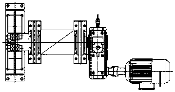
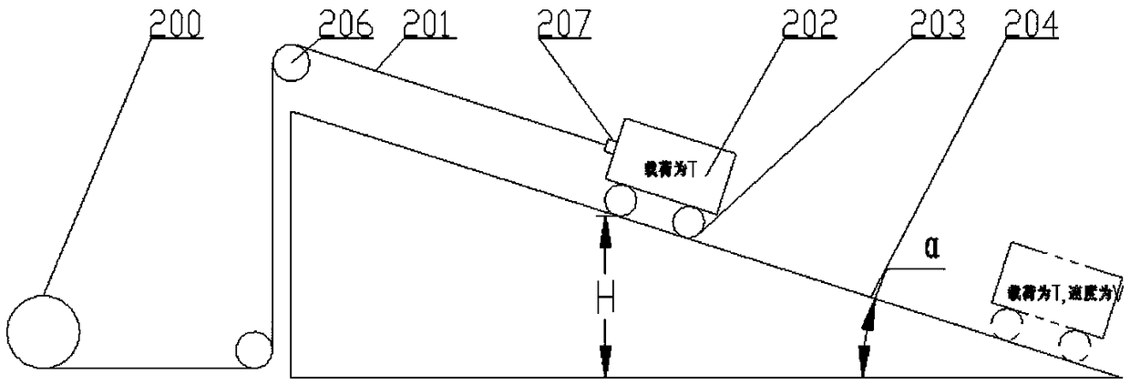
[0054] By setting the information acquisition element on the output shaft of the drum of the intelligent hoisting device, the moving speed and position information of the load vehicle lifted by the wire rope on the drum can be obtained;

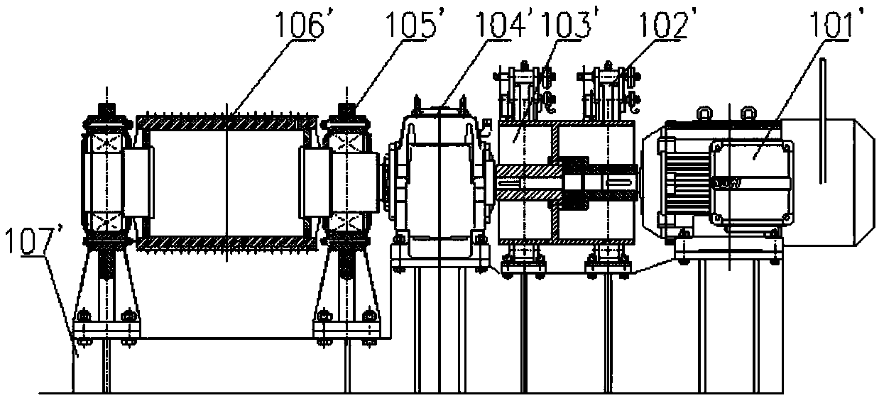
[0055] By setting the caliper disc brake on the output shaft of the reel, it provides braking force for the moving load vehicle;

[0056] Provide hydraulic oil for the caliper disc brake by connecting multiple hydraulic oil ports of the caliper disc brake to the hydraulic system with electromagnetic overflow valve, proportional pressure reducing valve and electromagnetic reversing valve respectively;

[0057] By connecting the hydraulic system, information acquisition components and the control system separately, the control system controls one or more of the electromagnetic overflow valve, proport...


PUM


Abstract

The invention discloses a method for lifting and releasing a descending mechanism through an intelligent winch device. The method comprises the following steps that an information acquisition elementis arranged on an output shaft of a winding drum, the movement speed and position information of a load vehicle which is lifted through the winding drum are acquired; a caliper disc brake is arrangedon the output shaft of the winding drum; a plurality of hydraulic oil ports of the caliper disc brake are connected with a hydraulic system provided with an electromagnetic overflow valve, a proportional pressure reducing valve and an electromagnetic reversing valve correspondingly; the hydraulic system, the information acquisition element and the control system are connected correspondingly, thecontrol system is enabled to control one or more of the electromagnetic overflow valve, the proportional pressure reducing valve and the electromagnetic reversing valve to act according to the movement speed and the position of the load vehicle, the oil supply pressure of the hydraulic system to the caliper disc brake is adjusted so as to adjust the brake torque of the caliper disc brake to the load vehicle. According to the method, the caliper disc brake directly brakes the output shaft of the winding drum, the brake torque is large and adjustable, so that the caliper disc brake is suitable for braking the large load, and the speed reducing and braking effects on the load vehicle are improved.

Description

technical field [0001] The invention relates to the field of mechanical technology, in particular to a method for lifting and releasing a lowering mechanism through an intelligent hoisting device. Background technique [0002] In the prior art, when carrying out collision tests on heavy load vehicles, the following methods are often used: figure 1 The shown system lifts and releases the descending mechanism along a slope, which includes: a drive unit 200 with a wire rope 201, a fixed pulley 206, a release device 207 connected to the end of the wire rope 201, and a load car 202 detachably connected to the release device 207, Roller wheels 203 are arranged at the bottom of the load cart 202, and the release device connecting the load cart and the wire rope is a lever release device. Wherein, a winch is used as a driving unit, and when the reel rotates, the load trolley 202 with a load T is lifted or lowered along the track slope 204 through a wire rope. [0003] In the prior...

Claims


Application Information

Patent Timeline
Patent Type & Authority Applications(China)
IPC IPC(8): B66D5/28B66D5/14B66D1/48F15B21/02
CPCF15B21/02B66D1/485B66D5/14B66D5/28
Inventor 邢伟刘占卿王迎东江鹏王坚傅常海魏从旗常嵩鲍加铭崔麦香
Owner 63921部队
Why Eureka
Try Eureka