Self-centering hole inner clamping device capable of achieving automatic compensation and tension maintaining during part heating

An automatic compensation and self-centering technology, applied in workpiece clamping devices, auxiliary devices, metal processing equipment, etc. The effects of axial displacement and radial runout, guaranteed processing quality and accurate positioning

Active Publication Date: 2018-12-07
CHONGQING CHUANYI CONTROL VALVE
View PDF10 Cites 0 Cited by
  • Summary
  • Abstract
  • Description
  • Claims
  • Application Information

AI Technical Summary

Problems solved by technology

The heating temperature of the parts is high, which will cause changes in the size and shape of the parts, which will easily lead to the loss of the clamping effect of the clamping device of the parts, the axial displacement or radial runout of the parts, and even the occurrence of parts and clamps. holding device falling off
It is especially serious for the clamping device in the hole of the ball and pipe parts. The aperture diameter of the part will change after heating. However, the current device used for the clamping device in the hole of the part does not have the automatic radial adjustment with the change of the aperture of the part. The function of compensating and maintaining tension often leads to the phenomenon of loose clamping or jamming of parts, resulting in poor spray welding effect and unqualified quality of parts. Once stuck, the clamping device and the product will be damaged at the same time

Method used


Image

  • Self-centering hole inner clamping device capable of achieving automatic compensation and tension maintaining during part heating
  • Self-centering hole inner clamping device capable of achieving automatic compensation and tension maintaining during part heating
  • Self-centering hole inner clamping device capable of achieving automatic compensation and tension maintaining during part heating

Examples


Embodiment Construction

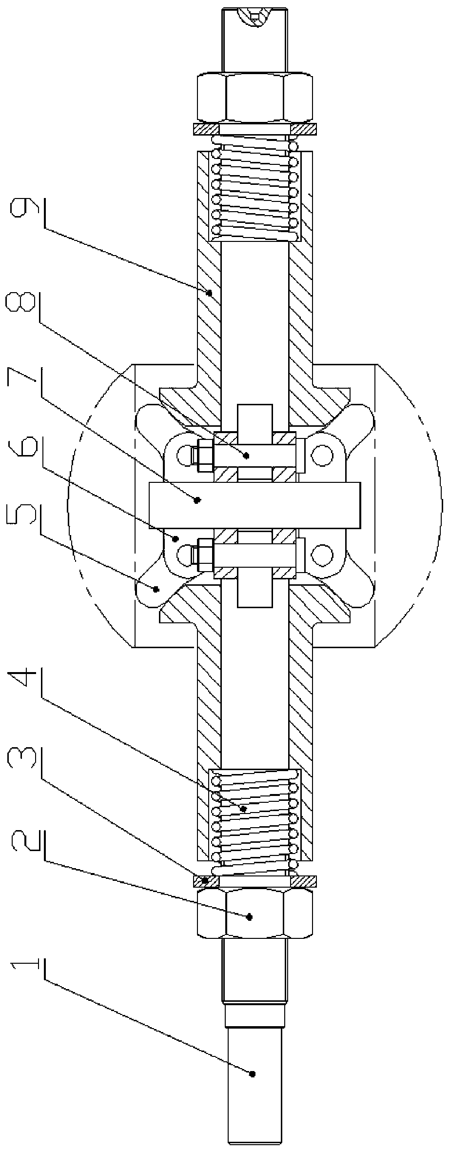
[0035] see Figure 1 to Figure 9 , a self-centering hole clamping device that automatically compensates and maintains tension when the part is heated, including a centering shaft 1, and a flange 7 for installing an expansion claw 5 is provided on the centering shaft 1, and the protrusion The circumference of the edge 7 is provided with a lifting groove 7-1. The hoisting groove 7-1 has facilitated the hoisting and hoisting of larger parts, and the hoisting groove 7-1 has formed a way for the iron chain when passing through the part endoporus. At least three hinged seats 6 are evenly distributed around the axis on the axial end surface of the flange 7 , each hinged seat 6 is hinged with an expansion claw 5 respectively. The hinged seat 6 includes two symmetrically arranged brackets 6-1, and the expansion claw 5 is arranged between the two brackets 6-1. The fixed end 5-2 of the expansion claw 5 and the hinged seat 6 are hinged by bolts 8, and the two brackets 6-1 of the hinged ...


PUM


Abstract

The invention relates to a self-centering hole inner clamping device capable of achieving automatic compensation and tension maintaining during part heating. The device comprises a centering shaft, aflange used for mounting expansion claws is arranged on the centering shaft, at least three hinging bases are uniformly distributed on the shaft end surface of the flange, the expansion claws are hinged to the hinging bases respectively, the fixed ends of the expansion claws are hinged to the hinge bases through bolts, and the free ends of the expansion claws extend out of the hinge bases; the shaft section of the centering shaft is sleeved with a jacking sleeve, and a push plate used for pushing the free ends of the expansion claws to move is arranged at the front end of the jacking sleeve. Aguide surface is arranged on the push plate, a pre-tightening spring is arranged at the rear end of the jacking sleeve, and the pre-tightening spring sleeves the shaft section of the centering shaftand is tightly pressed by a compression nut matched with the centering shaft through threads, so that the push plate of the jacking sleeve pushes the free ends of the expansion claws to do tensioningmotion and is used for tensioning and fixing a part from a part inner hole. The hole inner clamping device can conduct automatic radial compensated clamping along with aperture changes of the heated part, part clamping is stable, and the device has a self-centering function and is accurate in part positioning.

Description

technical field [0001] The invention relates to a clamping device, in particular to a clamping device in a self-centering hole which automatically compensates and maintains tension when parts are heated. Background technique [0002] At present, heat treatment of parts due to special requirements is a relatively common process, including the heating of parts in the thermal spray welding process. Thermal spray welding is a process that uses a certain heat source to spray and weld the hard alloy layer on the surface of the part. During the spray welding process, the parts and the coating need to be heated. Generally, the hard alloy layer can be made at 900 ° C or higher. The alloy layer and the part matrix are remelted. The heating temperature of the parts is high, which will cause changes in the size and shape of the parts, which will easily lead to the loss of the clamping effect of the clamping device of the parts, the axial displacement or radial runout of the parts, and ...

Claims


Application Information

Patent Timeline
Patent Type & Authority Applications(China)
IPC IPC(8): B23K37/053B25B11/00
CPCB23K37/053B25B11/00
Inventor 许波尚洪宝王扬李黎
Owner CHONGQING CHUANYI CONTROL VALVE
Why Eureka
Try Eureka