Speed regulating device for rotating arm of single cylinder turbine

A technology of a speed regulating device and a rotating arm, which is applied in mechanical equipment, engine components, engine control, etc., can solve the problems of waste of hardware resources, inability to satisfy, and the control system cannot work well in coordination, and achieves convenient operation and simple structure. Effect

Inactive Publication Date: 2018-12-04
叶丛杰
View PDF0 Cites 0 Cited by
  • Summary
  • Abstract
  • Description
  • Claims
  • Application Information

AI Technical Summary

Problems solved by technology

[0002] The speed of the steam turbine is adjusted by changing the steam injection volume. During normal operation, the output power of the steam turbine can meet the external load requirements by changing the steam intake of the steam turbine. If the turbine speed is not adjusted, when When the external load becomes larger or smaller, there will be large fluctuations, which will cause the output power of the steam turbine to be unstable and unable to meet the operation requirements. Therefore, the steam turbine must be equipped with a speed adjustment device so that the adjusted speed is within the allowable range. The steam turbine speed regulation is mostly controlled by an electronic governor or an independent automatic control system, which causes a waste of hardware resources or the control systems are independent of each other and cannot coordinate well. Self-regulating single-cylinder steam turbine rotary arm speed control device

Method used


Image

  • Speed regulating device for rotating arm of single cylinder turbine
  • Speed regulating device for rotating arm of single cylinder turbine

Examples


Embodiment Construction

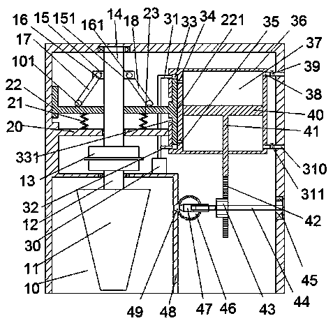
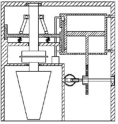
[0009] Combine below Figure 1-2 The present invention will be described in detail.

[0010] refer to Figure 1-2, according to an embodiment of the present invention, a single-cylinder steam turbine rotary arm speed control device includes a main casing, a turbine chamber 10 is provided at the lower left part of the main casing, and a turbine 11 is arranged in the turbine chamber. 11 is connected with the power rotating shaft 12 in power cooperation. The power rotating shaft 12 is located on the upper part of the turbine 11. The power rotating shaft 12 is rotatably arranged in the top wall of the turbine cavity 10. The upper end of the power rotating shaft 12 extends upward and is connected with the deceleration The reducer 13 is rotated and connected, the reducer 13 is located at the lower side of the fixed plate 20, the fixed plate 20 is extended horizontally, and the left extension end of the fixed plate 20 is fixedly connected with the left side wall of the main box. Th...


PUM


Abstract

The invention discloses a speed regulating device for a rotating arm of a single cylinder turbine. The device comprises a main box body. A turbine cavity is formed in the lower part of the left side in the main box body, a speed reducer is arranged on the upper part of the turbine cavity, an oil pump is arranged on the right part of the speed reducer, a fixed plate is arranged on the upper part ofthe speed reducer, a first fixed spring and a second fixed spring are arranged on the fixed plate, a transverse sliding plate is arranged at the upper end of each spring, a rotating arm is arranged on the upper part of the transverse sliding plate, a hydraulic cylinder is arranged on the right side of the rotating arm, a sliding cavity is formed in the left side wall of the hydraulic cylinder, asecond rotating shaft is arranged at the bottom of the hydraulic cylinder, a gear is arranged on the second rotating shaft, an air injection cavity is formed in the left side of the gear, a slide block is arranged in the air injection cavity, and the slide block can regulate the size of an air injection nozzle, so that the rotating speed of the turbine is regulated to achieve the regulating purpose.

Description

technical field [0001] The invention relates to the technical field of steam turbine speed regulation, in particular to a single-cylinder steam turbine rotary arm speed regulation device. Background technique [0002] The speed of the steam turbine is adjusted by changing the steam injection volume. During normal operation, the output power of the steam turbine can meet the external load requirements by changing the steam intake of the steam turbine. If the turbine speed is not adjusted, when When the external load becomes larger or smaller, there will be large fluctuations, which will cause the output power of the steam turbine to be unstable and unable to meet the operation requirements. Therefore, the steam turbine must be equipped with a speed adjustment device so that the adjusted speed is within the allowable range. The steam turbine speed regulation is mostly controlled by an electronic governor or an independent automatic control system, which causes a waste of hardw...

Claims


Application Information

Patent Timeline
Patent Type & Authority Applications(China)
IPC IPC(8): F01D17/14F01D17/26F01D17/20
CPCF01D17/14F01D17/20F01D17/26F05D2270/02
Inventor 叶丛杰
Owner 叶丛杰
Why Eureka
Try Eureka