Eureka AIR delivers breakthrough ideas for toughest innovation challenges, trusted by R&D personnel around the world.

A sound box with an easy-to-cool structure

A cooling structure and speaker technology, applied in the transducer shell/cabinet/stand and other directions, can solve the problems of poor heat dissipation effect of the speaker, inability to seal the ventilation holes, etc., and achieve the effect of convenient heat dissipation, good heat dissipation effect, and good use effect.

Active Publication Date: 2019-10-15
宁波志豪塑业有限公司
View PDF7 Cites 0 Cited by
  • Summary
  • Abstract
  • Description
  • Claims
  • Application Information

AI Technical Summary

Problems solved by technology

[0004] The invention proposes a sound box with an easy-to-cool structure, which solves the problem that the existing sound box has poor heat dissipation effect and cannot seal the ventilation holes when heat dissipation is not performed

Method used


Image

  • A sound box with an easy-to-cool structure
  • A sound box with an easy-to-cool structure
  • A sound box with an easy-to-cool structure

Examples


Embodiment 1

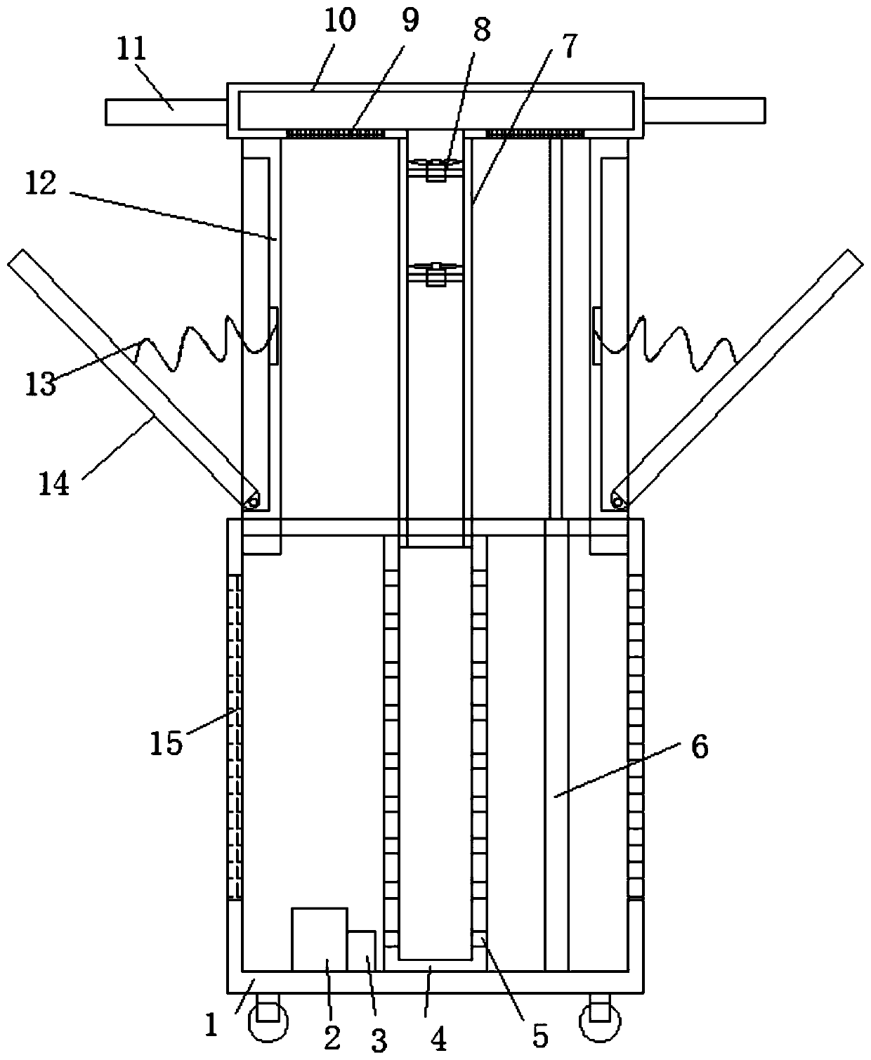
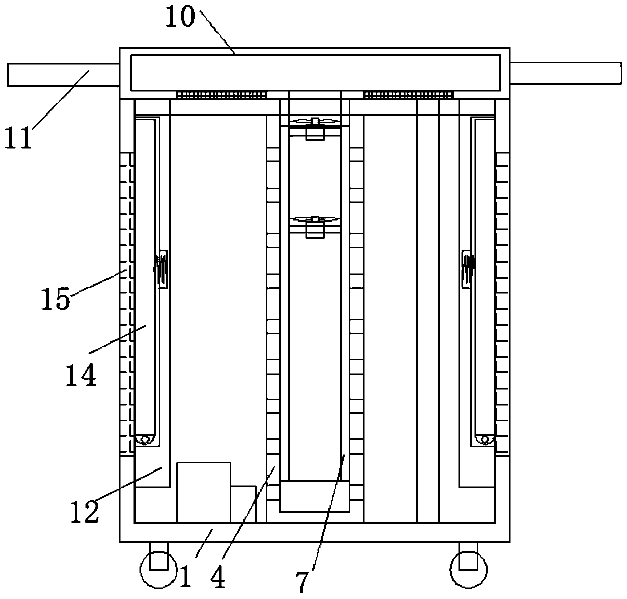
[0031]Embodiment 1: The circulating heat pipe 19 is located on the side wall of the circuit board, and heat-conducting silica gel is arranged between the circulating heat pipe 19 and the circuit board. When in use, the telescopic column 6 is controlled by the controller, and the output shaft of the telescopic column 6 Drive the top cover 10 to move upward continuously, the top cover 10 drives the air duct 7 to slide in the air outlet tube 4, and simultaneously drives the movable plate 12 to continuously move upward, so that the air inlet hole 9 and the air outlet hole are all opened, the fan 8 is started, and the The outside air is introduced into the top cover 10 through the air inlet hole 9, and then enters the air outlet tube 4 through the air guide pipe 7 and is ejected from the air guide hole 5, taking away the heat on the components in the speaker body 1, and passing through the air outlet hole. In this way, the internal parts in the speaker can be dissipated in an all-ro...

Embodiment 2

[0032] Embodiment 2: The circulating heat pipe 19 is located on the side wall of the frequency converter, or wound on the frequency converter, and heat-conducting silica gel is provided between the circulating heat pipe 19 and the frequency converter. When in use, the action of the telescopic column 6 is controlled by the controller , the output shaft of the telescopic column 6 drives the top cover 10 to move upward continuously, the top cover 10 drives the air duct 7 to slide in the air outlet tube 4, and simultaneously drives the movable plate 12 to move upward continuously, so that the air inlet hole 9 and the air outlet hole are evenly spaced. Open it, start the fan 8, introduce the outside air into the top cover 10 through the air inlet hole 9, then enter the air outlet tube 4 through the air guide pipe 7 and spray out from the air guide hole 5, and take away the internal parts of the speaker body 1. The heat is discharged through the air outlet, so that the internal parts...


PUM


Abstract

The invention belongs to the field of sound boxes, particularly relates to a sound box with an easily-cooled structure, aims at the problems that an existing sound box has poor heat dissipation effectand ventilation holes cannot be sealed when heat dissipation is not carried out, and provides the following scheme that the sound box comprises a sound box body, wherein air outlet holes are arrangedin the side walls of the two sides of the sound box body; a dustproof net is arranged inside the air outlet holes; a vertically-arranged air outlet cylinder is arranged in the sound box body; a plurality of air guide holes which are uniformly distributed are arranged in the outer side wall of the air outlet cylinder; the interior of the air outlet cylinder is connected to a vertically-arranged air guide pipe in a sliding mode; a plurality of fans are installed inside the air guide pipe; and the top end of the air guide pipe is connected to a top cover arranged above the sound box body. According to the sound box, local heat dissipation and overall heat dissipation of the sound box can be achieved, a heat dissipation effect is good, and meanwhile, when the sound box is not used, the ventilation holes can be sealed, the damage of moisture of outside air to parts inside the sound box can be reduced, and a use effect is good.

Description

technical field [0001] The invention relates to the technical field of sound boxes, in particular to a sound box with an easy-to-cool structure. Background technique [0002] Sound refers to sounds other than human language and music, including sounds from the natural environment, animals, machines and tools, and various sounds from human actions. In 1906, the American De Forest invented the vacuum triode, creating a precedent for human electroacoustic technology. Audio equipment consists of sound sources (music playback equipment, pickup equipment, namely microphones), control equipment analog or digital mixers, audio processors (previously used effectors, equalizers, compressors, frequency dividers, signal distribution Devices, delayers and other peripheral equipment, and now there are digital system controllers that integrate the above functions), power amplifiers, and speakers. To be precise, the combined audio system is the integrated audio set machine launched by the...

Claims


Application Information

Patent Timeline
Patent Type & Authority Patents(China)
IPC IPC(8): H04R1/02
Inventor 张俊阳
Owner 宁波志豪塑业有限公司
Why Eureka
Eureka Blog
Learn More