Phase-change switch structure

A technology of commutation switches and static contacts, which is applied in the direction of electric switches, electrical components, circuits, etc. It can solve the problems of easy burnout of contacts, complex interlock mechanism, weak arc extinguishing ability, etc., and achieve short-term current tolerance Strong ability, increased contact area, and improved electrical life

Pending Publication Date: 2018-11-30
福建尤伯科技有限公司
View PDF19 Cites 0 Cited by
  • Summary
  • Abstract
  • Description
  • Claims
  • Application Information

AI Technical Summary

Problems solved by technology

Chinese patent CN201711383820.3 discloses a three-phase commutation relay combination structure with self-locking function, which uses two relays with an interlock mechanism to perform commutation operations, but due to the small opening distance and contact pressure of the relays And other restrictions, also need a relay incoming line load switching operation
[0004] 1. The logic control for controlling the closing and opening of the three relays is relatively complicated and requires a complex interlocking mechanism;
[0005] 2. The relay may have the problem of contact bonding, and when the contact of a certain relay is bonded, one of the other two relays will be closed and there will be a short circuit between phases;
[0006] 3. Limited by the structure of the relay, the contact opening distance of the relay is generally 1.2mm, which is much lower than the contact opening distance of the switch in the distribution line (typical value is 4mm), and the arc extinguishing ability is weak; in addition, the contact pressure of the relay Generally, it is 2~3N, which is much lower than the contact pressure of the switch in the power distribution line (typical value is 5N). When the circuit has a short-circuit current, the contact of the relay will be opened before the switch and arc; so this kind of When the combined structure of the three-phase commutation relay with self-locking function is used in such occasions of tens to hundreds of amps, the contacts of the relay are easy to burn out or weld

Method used


Image

  • Phase-change switch structure
  • Phase-change switch structure
  • Phase-change switch structure

Examples


Embodiment Construction

[0042] In order to further explain the technical solution of the present invention, the present invention will be described in detail below through specific examples.

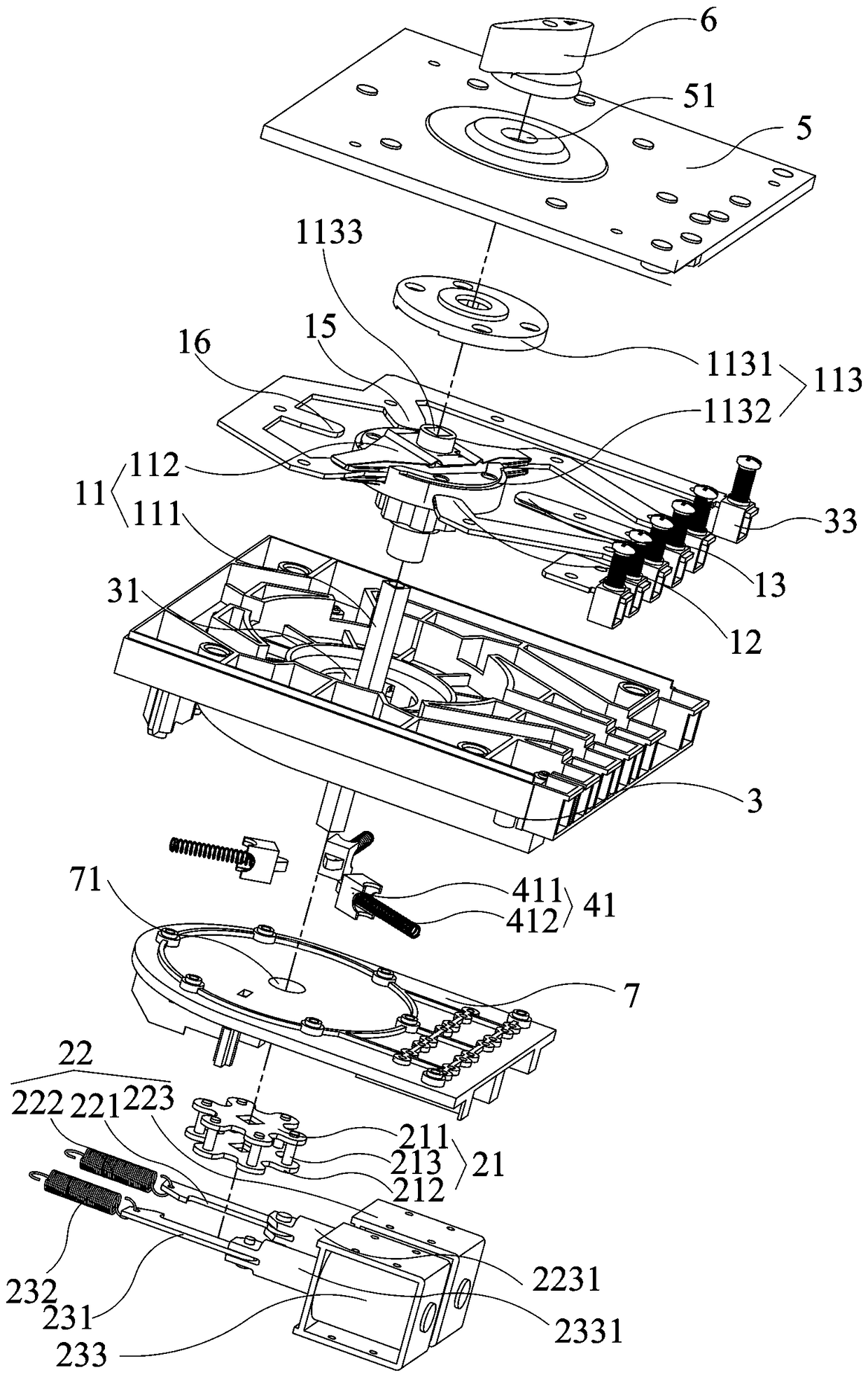
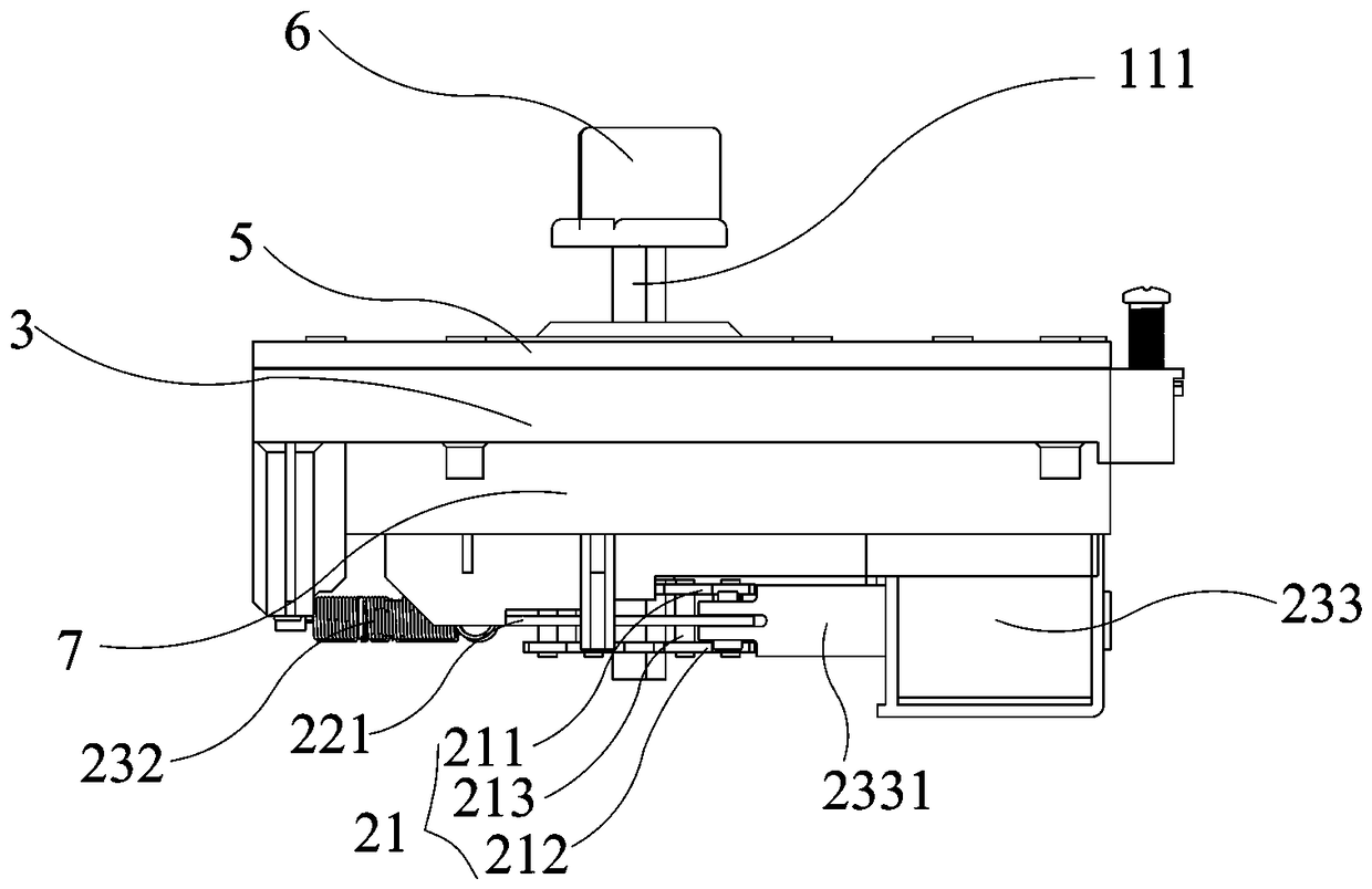
[0043] like Figure 1 to Figure 13 As shown, the present invention discloses a phase change switch structure, which includes a contact system 1 , a driving device 2 and a support plate 3 .

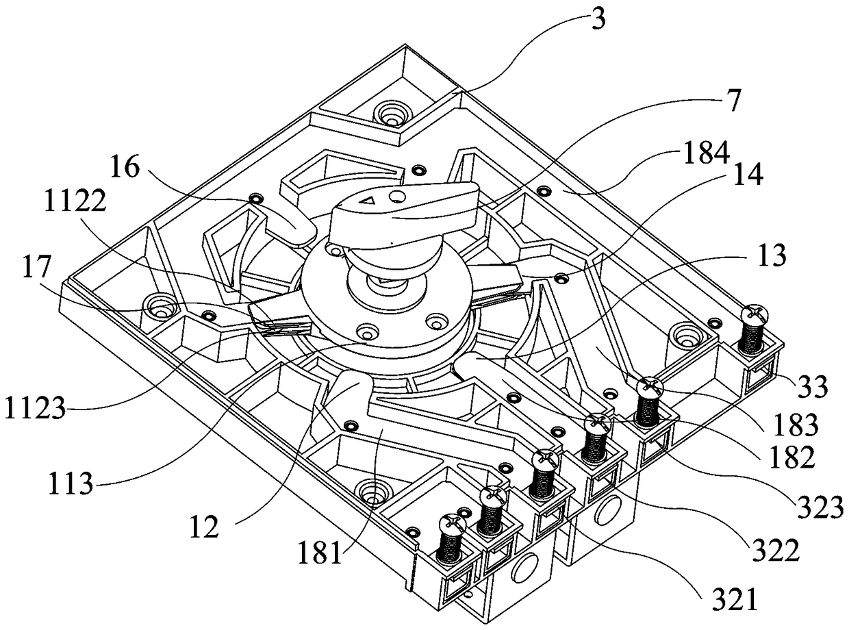
[0044] Specifically, cooperate figure 1 , image 3 and Figure 5 As shown, the contact system 1 includes six static contacts and a moving contact assembly 11; wherein the moving contact assembly includes a rotating shaft 111 and a moving contact 112 fitted on the rotating shaft 111, the moving contact 112 is axisymmetric about the rotating shaft 111; the six static contacts are distributed at equal intervals around the center of the moving contact 112, and the six static contacts include the first input static contacts 12 for connecting with the three phase lines of the three-phase electricity respectively. , the second...


PUM


Abstract

The invention discloses a phase-change switch structure. The phase-change switch structure comprises a contact system, wherein the contact system comprises six static contacts and one movable contactassembly; the movable contact assembly comprises a movable contact and a rotating shaft connected with the center of the movable contact; the six static contacts are distributed in a circumferential equidistant manner with respect to the center of the movable contact; the six static contacts include a first input static contact, a second input static contact and a third input static contact for being connected with three phase lines with three-phase electric power respectively as well as a first output static contact, a second output static contact and a third output static contact used for being connected with a load; the first output static contact, the second output static contact and the third output static contact are opposite to the first input static contact, the second input staticcontact and the third input static contact; and the two ends of the movable contact are in movable contact with the six static contacts. The phase-change switch structure is safe and reliable, and can avoid the situation of interphase short circuit.

Description

technical field [0001] The invention relates to a phase change switch, in particular to a phase change switch structure. Background technique [0002] The role of the commutation switch device in the power supply system is to switch the power load, reduce the three imbalances of the power supply transformer and the transmission line, improve the power supply efficiency, and improve the power supply environment. [0003] At present, the general commutation switch is generally realized by multiple relays (single-phase switch), and the commutation operation is performed by controlling whether the A phase, the B phase, and the C phase are connected or not, so as to reduce the degree of unbalanced three-phase load. Chinese patent CN201711383820.3 discloses a three-phase commutation relay combination structure with self-locking function, which uses two relays with an interlock mechanism to perform commutation operations, but due to the small opening distance and contact pressure o...

Claims


Application Information

Patent Timeline
Patent Type & Authority Applications(China)
IPC IPC(8): H01H9/00
CPCH01H9/0016
Inventor 黄茂源杨平孝
Owner 福建尤伯科技有限公司
Why Eureka
Try Eureka