Orientated detection device for density of solution

A detection device and solution technology, applied in the direction of material analysis by measuring buoyancy, can solve the problems of unfavorable quality control, waste of resources, and high sampling frequency, achieve automatic and continuous production, avoid production interruption, and reduce false triggers. Effect

Pending Publication Date: 2018-11-30
GUIZHOU KAILIN GRP CO LTD
View PDF0 Cites 2 Cited by
  • Summary
  • Abstract
  • Description
  • Claims
  • Application Information

AI Technical Summary

Problems solved by technology

This process cannot realize the continuous inspection by inspectors, and the inspection interval is usually half an hour or once an hour
If the detection is not timely, it will affect the continuity of process industry production and lead to unstable quality
[0003] For example, in the process of wet phosphoric acid concentration, 23% dilute phosphoric acid needs to be concentrated and evaporated into 46% concentrated phosphoric acid; as an intermediate product in the production of subsequent diammonium phosphate products, its mass fraction is controlled at 46%; if the mass fraction is lower than 46%, Then a large amount of excess water is brought into the follow-up process, which affects the production control index of DAP and the appearance of the formed particles, and quality accidents are prone to occur; the mass fraction is too high, which greatly wastes resources and is not conducive to the subsequent control of DAP production indicators
Under the current conditions, there are no measurement and detection devices and systems that are well suited to this process, and the manual sampling method is basically used to measure the specific gravity. With the fluctuation of the control index, there is a large time deviation (half an hour) in the operation process of this method. or take samples once an hour), the sampling frequency is high, if the workers are busy with other things and fail to take samples in time, it will cause the problem of high quality scores. This method makes the product quality scores fluctuate all the time, which is not conducive to quality control. Affect product quality, but no better way to solve this problem has been found

Method used


Image

  • Orientated detection device for density of solution
  • Orientated detection device for density of solution
  • Orientated detection device for density of solution

Examples


Embodiment Construction

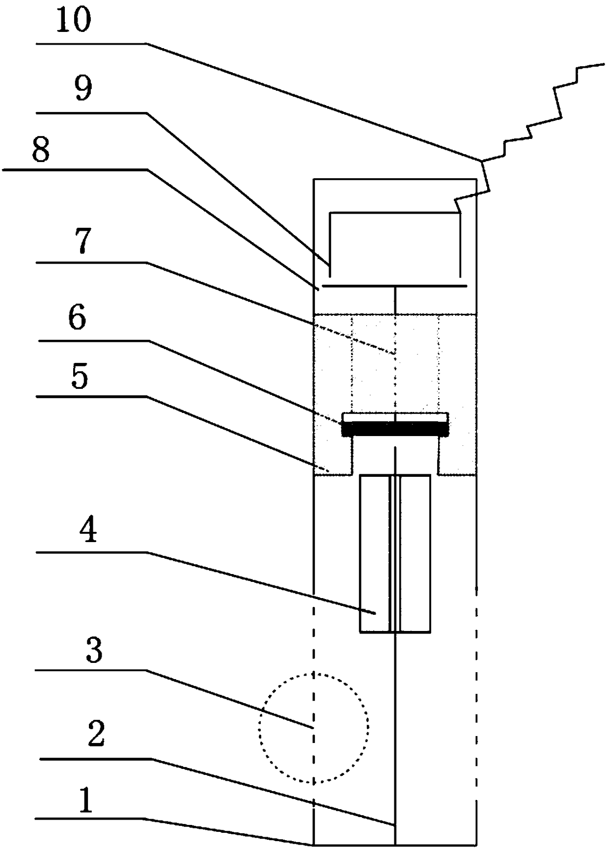
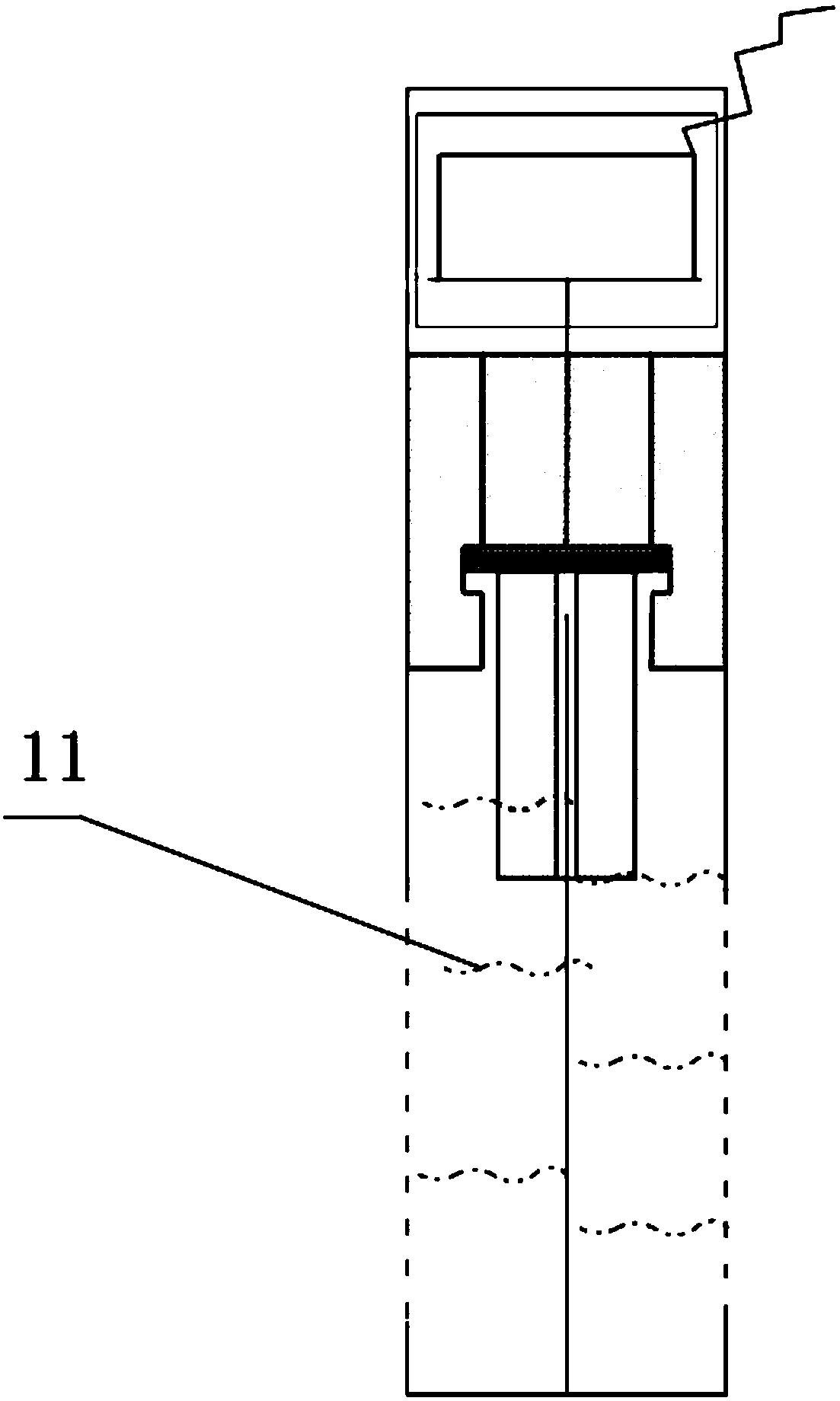
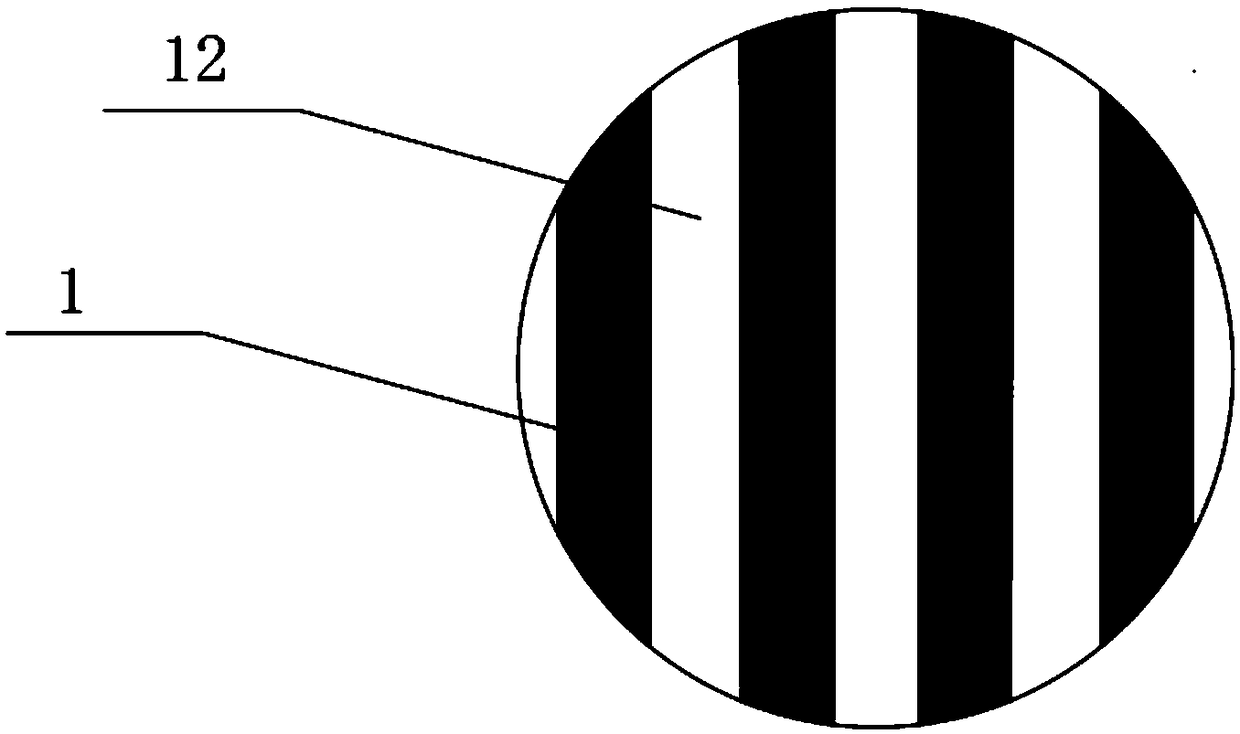
[0029] like Figure 1 to Figure 5 As shown, a solution density orientation detection device includes a floating ball 4 that can move along the guide rod 2, the floating ball 4 is placed in the cavity in the shell 1, and is arranged in sequence in the shell 1 away from the end of the guide rod 2 There are a signal trigger 6 and a signal contactor 9, and the signal contactor 9 is connected to the interface of the control system through a wire 10. The side surface 3 of the casing 1 is provided with a solution inlet and outlet 12 communicating with the cavity. The solution inlet and outlet 12 are a plurality of square slots parallel to the guide rod 2 and distributed on the side surface of the casing 1 at equal intervals. One end of the guide rod 2 is fixedly connected to the casing 1, and the other end is a free end. The floating ball 4 is a cylinder 14 with a guiding channel 13 along its own axis. The cylinder 14 includes an annular vacuum chamber 15 positioned on the outside,...


PUM


Abstract

The invention discloses an orientated detection device for the density of a solution. The device comprises a floating ball (4) capable of moving along a guiding rod (2), the floating ball (4) is placed in a cavity in a shell (1), a signal trigger (6) and a signal contactor (9) are sequentially arranged at one end, away from the guiding rod (2), in the shell (1), and the side surface (3) of the shell (1) is provided with a solution feeding and discharging opening (12) communicated with the cavity. The device solves the density detection problem of a concentrated solution, realizes continuous production, reduces the quality instability of the concentrated solution, and stably improves the economic value creation efficiency.

Description

technical field [0001] The invention relates to a solution density detection device, in particular to a density detection device of a solution concentration device. Background technique [0002] In the existing industrial production, the solution concentration process often occurs, but there is no good online monitoring method at present. The common method is to manually use a density meter to detect the solution density, meet the required requirements, and then discharge the solution into the next process. Then, continue to add dilute solution in the concentration equipment, and concentrate again. This process cannot realize the continuous inspection by inspectors, and the inspection interval is usually half an hour or once an hour. If the detection is not timely, it will affect the continuity of process industry production and lead to unstable quality. [0003] For example, in the process of wet phosphoric acid concentration, 23% dilute phosphoric acid needs to be concen...

Claims


Application Information

Patent Timeline
Patent Type & Authority Applications(China)
IPC IPC(8): G01N9/08
CPCG01N9/08
Inventor 杨阳陈彬梅桂彭学江周英霞胡黔
Owner GUIZHOU KAILIN GRP CO LTD
Why Eureka
Try Eureka