A high-power low-pulsation lobe rotor pump

A cam rotor pump, high-power technology, used in rotary piston pumps, rotary piston/oscillating piston pump components, pumps, etc., can solve the problem of reducing the service life of the unit, reducing the service life of shaft, bearing and seal, transmission The problem of large amplitude of axial radial excitation force can reduce vibration and noise, ensure stable operation, and reduce equipment quality.

Active Publication Date: 2019-10-11
LANZHOU UNIVERSITY OF TECHNOLOGY
View PDF5 Cites 0 Cited by
  • Summary
  • Abstract
  • Description
  • Claims
  • Application Information

AI Technical Summary

Problems solved by technology

At present, the rotors of the lobe pumps generally adopt a solid structure. With the improvement of the performance requirements of the lobe pumps, the size of the lobe pumps and the size of the rotors also increase, and the self-weight of the rotors increases accordingly. The amplitude of the radial excitation force on the transmission shaft is very large, and the increase in the weight of the rotor also affects the bearing and axial seal, reducing the service life of the shaft, bearing and seal
The gap between the rotor and the pump chamber of the cam pump is generally a fixed gap. During the working process, the volume of the suction and discharge chamber changes periodically with the rotation of the transmission shaft. The working characteristics of the cam pump determine the flow and pressure generated during the working process. Pulsation, when the pulsation frequency of the rotor is close to the natural frequency of the pump unit, the resonance of the unit will be induced, which may cause damage to the internal parts of the unit, and cause large noise and vibration at the same time, affecting the performance of the unit and reducing the service life of the unit

Method used


Image

  • A high-power low-pulsation lobe rotor pump
  • A high-power low-pulsation lobe rotor pump
  • A high-power low-pulsation lobe rotor pump

Examples


specific Embodiment

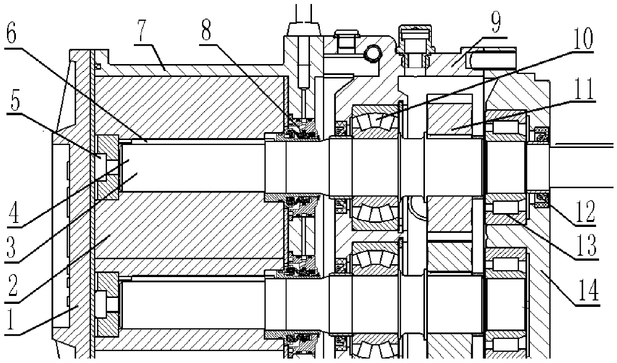
[0048] Specific embodiment: According to an example of a 1200 cubic large displacement rotor pump, the diameter of the rotor base circle is 450 mm, the software analysis shows that the mass of the solid rotor body of the pump is about 306.426 kg, and the mass of the rotor body with a hollow structure is 208.773 kg . From software analysis, it can be seen that the weight of the rotor as hollow is reduced compared with the original solid rotor: 306.426kg-208.773kg=97.653kg, and the weight is reduced by about 32%; r When =0.1mm, the radial force of the high-pressure end of the gradual gap rotor chamber to the rotor in the y direction is significantly lower than that of the equal-gap rotor. The maximum radial force is 6.7kN, which is less than that of the equal-gap rotor. It is 12% smaller, and the radial force in the x direction of the gradual clearance rotor cavity is 4.4kN, which is 19% smaller than that of the equal clearance rotor.


PUM


Abstract

The invention relates to the technical field of cam pump with large flow and large power, particularly relates to a cam rotor pump with large power and low pulsation. The cam rotor pump is characterized by comprising two same rotors arranged in a cavity, the rotors are circumferentially and fixedly arranged on a rotary shaft through key groove, the rotors are axially fixed on the rotary shaft through a locking nut and a locking block, the side surface of the cavity is provided with a pump cover corresponding to the rotor; a 0 to 0.2 mm gap is formed between the rotor and the cavity, the rotaryshaft is fixed on a gearbox through a double-row tapered roller bearing and a cylindrical roller bearing, the two rotary shaft rotates at same rotary speed through the engaging between two synchromesh gears, a 0.4 mm gap is formed between two rotors, the side surface of the gearbox is provided a gearbox cover, a mechanical sealing mechanism is arranged on the connection part of the rotary shaft and the cavity, a rubber oil sealing is arranged on the connection part of the rotary shaft and the gearbox cover. According to the cam rotor pump, the operation of equipment is stable, a transition line is adopted for a chamber-wall line, the flowing of a flow in the pump is optimized, the pulsation phenomenon of the flow is greatly reduced,and the noise of vibration is reduced.

Description

technical field [0001] The invention relates to the technical field of high-flow and high-power cam pumps, in particular to a high-power low-pulsation cam rotor pump. Background technique [0002] Lobe pumps are currently widely used in municipal sewage, petrochemical, flood fighting and disaster relief and other fields, with positive and negative rotation, high efficiency, strong self-priming and wear resistance. At present, the rotors of the lobe pumps generally adopt a solid structure. With the improvement of the performance requirements of the lobe pumps, the size of the lobe pumps and the size of the rotors also increase, and the self-weight of the rotors increases accordingly. The amplitude of the radial excitation force on the transmission shaft is very large. At the same time, the increase in the weight of the rotor also affects the bearing and axial seal, reducing the service life of the shaft, bearing and seal. The gap between the rotor and the pump chamber of the...

Claims


Application Information

Patent Timeline
Patent Type & Authority Patents(China)
IPC IPC(8): F04C2/12F04C15/00
Inventor 黎义斌郭东升杜俊张晓泽
Owner LANZHOU UNIVERSITY OF TECHNOLOGY
Why Eureka
Try Eureka