High salinity wastewater energy-saving evaporative crystallization system and technology thereof

A high-salt wastewater, evaporation and crystallization technology, applied in the directions of evaporation separation and crystallization, crystallization separation, solution crystallization, etc., can solve the problems of low energy utilization rate, many equipments used, high cost, etc., and solve difficult problems with a small number of equipments , the effect of small footprint

Pending Publication Date: 2018-11-30
SHANDONG TIANLI DRYING TECH & EQUIP
View PDF0 Cites 12 Cited by
  • Summary
  • Abstract
  • Description
  • Claims
  • Application Information

AI Technical Summary

Problems solved by technology

[0003] The existing high-salt wastewater evaporation and crystallization process usually adopts multi-effect evaporation followed by crystallization, or direct evaporation followed by crystallization. The above process mainly has the following disadvantages: 1. High energy consumption and low energy utilization rate, resulting in energy consumption per unit of wastewater treatment High, high cost; 2. There are many equipments used, the system occupies a large area, and the equipment investment is high; 3. The existing crystallization equipment is not targeted for the treatment of high-salt wastewater, and there are many deficiencies in the selection of materials

Method used


Image

  • High salinity wastewater energy-saving evaporative crystallization system and technology thereof

Examples


Embodiment 1

[0037] Embodiment one, taking ammonium sulfate-containing high-salt wastewater as an example:

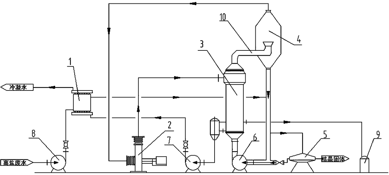
[0038]The ammonium sulfate wastewater is input into the system through the feed pump 8, and enters the wastewater preheater 1 to be preheated to 30-40°C. After preheating, it enters the tubes installed inside the heating chamber 3. 80-90°C, enter the evaporation chamber 4 from the top of the heating chamber 3, and flash in the evaporation chamber. After flashing, the remaining concentrated wastewater enters the heating chamber 3 through the circulation pump 6 for heating, and then enters the evaporation chamber 4 for flash evaporation after heating. During the cycle evaporation process, ammonium sulfate wastewater is supplemented. After multiple cycles, when the ammonium sulfate solution in the system reaches more than 40%, a supersaturated solution is formed and ammonium sulfate crystals begin to precipitate, and the ammonium sulfate wastewater with crystal precipitation is introduc...

Embodiment 2

[0041] Embodiment two, take sodium chloride-containing wastewater as an example:

[0042] The sodium chloride wastewater is input into the system through the feed pump 8, enters the wastewater preheater 1 to be preheated to 30-40°C, and enters the heating chamber 3 after preheating, and the sodium chloride wastewater reaches 80-90°C after heat exchange through the tubes. ℃, enters the evaporation chamber 4 from the top, and flashes in the evaporation chamber. After flashing, the remaining concentrated wastewater enters the heating chamber 3 to be heated through the circulation pump 6, and then enters the evaporation chamber 4 for flash evaporation after heating. During the cycle evaporation process, Add sodium chloride wastewater. After several cycles, when the sodium chloride solution in the system reaches more than 28%, a supersaturated solution is formed and sodium chloride crystals begin to precipitate, and the sodium chloride wastewater with crystal precipitation is introd...

Embodiment 3

[0045] Embodiment three, take the example that contains sodium gluconate waste water:

[0046] Sodium gluconate waste water enters the system through the feed pump 8, enters the waste water preheater 1 to preheat to 30-40°C, and enters the heating chamber 3 after preheating, and the sodium gluconate waste water reaches 80-90°C after heat exchange through the tubes ℃, enters the evaporation chamber 4 from the top, and flashes in the evaporation chamber. After flashing, the remaining concentrated wastewater enters the heating chamber 3 to be heated through the circulation pump 6, and then enters the evaporation chamber 4 for flash evaporation after heating. During the cycle evaporation process, Add sodium gluconate wastewater, after several cycles, when the sodium gluconate solution in the system reaches more than 55%, a supersaturated solution is formed and sodium gluconate crystals begin to precipitate, and the sodium gluconate wastewater with crystal precipitation is introduce...


PUM


Abstract

The invention provides a high salinity wastewater energy-saving evaporative crystallization system and a technology thereof. The system comprises a wastewater preheater, a heating chamber, an evaporation chamber, a steam compressor, a vacuum system, a solid-liquid separation device, a circulating pump, a feed pump, and a condensate water pump. High salinity wastewater enters the heating chamber for preheating, enters the evaporation chamber for steam heating, and undergoes flash evaporation under vacuum and at low pressure; the evaporated steam enters the steam compressor for compression and warming, and the compressed steam enters the heating chamber again to heat the wastewater; condensate water is then used to preheat the high salinity wastewater, and the heat taken away by the evaporated water is further recovered. The heating chamber and the evaporation chamber of the invention adopt an integrated structure, the wastewater directly enters the evaporation chamber for flash evaporation after being heated, the concentrated liquor enters the circulating pump through the bottom of the evaporation chamber to be circulated to the heating chamber for continuous heating, and the liquidforms an inner circulation until the crystallization starts. The invention has the advantages of energy conservation and high efficiency, small equipment occupation, less equipment investment, etc.,and zero discharge of wastewater is finally achieved.

Description

technical field [0001] The invention relates to the technical field of environmental protection and energy saving, in particular to a system and process for recycling latent heat and sensible heat of evaporation in the treatment of high-salt wastewater, which is suitable for the process of evaporation and crystallization in the treatment of high-salt wastewater. Background technique [0002] High-salt wastewater has complex components, high toxicity, and is difficult to treat. If it is not treated, it will cause serious pollution to the environment. Evaporation and crystallization technology can effectively separate salt from solution in the treatment of high-salt wastewater, and both evaporated water and separated salt can be recycled and reused to meet the requirement of zero discharge of high-salt wastewater. At the same time, during the concentration and crystallization process of salty wastewater, a large amount of water evaporates, and the evaporated water takes away a...

Claims


Application Information

Patent Timeline
IPC IPC(8): C02F1/04C02F1/06B01D9/02
CPCB01D9/0004B01D9/0013B01D9/0031B01D9/0059C02F1/041C02F1/043C02F1/048C02F1/06B01D2009/0086
Inventor 柴本银王寿权尹凤交张自督隋丽红
Owner SHANDONG TIANLI DRYING TECH & EQUIP
Why Eureka
Try Eureka