Automatically-controlled cement mixing device based on electric cabinet

A technology of mixing equipment and electric control box, which is applied in the direction of cement mixing device, control device, clay preparation device, etc. It can solve the problems of uneven and insufficient mixing of stirred items, inability to control the stirring temperature of the mixing box, and insufficient stirring at the central position, etc. problem, to achieve the effect of simple structure, eliminating temperature drift and increasing work efficiency

Inactive Publication Date: 2018-11-30
四川双利新材料有限公司
View PDF4 Cites 0 Cited by
  • Summary
  • Abstract
  • Description
  • Claims
  • Application Information

AI Technical Summary

Problems solved by technology

[0002] There are many cement mixing devices for construction, which are generally the mixing chamber and the stirring rod in the chamber body. The stirring rod is equipped with blades, but this kind of stirring device has defects. The length of the stirring rod is fixed, and the position of the blade on it is also fixed, so it can only be used Fully stir the position where the blade is located, and the rest of the place is not sufficiently stirred. In addition, the position of the blade is fixed and cannot move up and down in the mixing chamber. Stirring at each height of the chamber body will easily make the mixing of the stirred items uneven and insufficient.
In addition, the size of the blades is limited. If the blades are too large, the stirring in the center will not be sufficient. If the blades are too small, the stirring around them will not be sufficient.
Moreover, the stirring temperature in the stirring box cannot be controlled, and the temperature control is not accurate

Method used


Image

  • Automatically-controlled cement mixing device based on electric cabinet
  • Automatically-controlled cement mixing device based on electric cabinet
  • Automatically-controlled cement mixing device based on electric cabinet

Examples


Embodiment

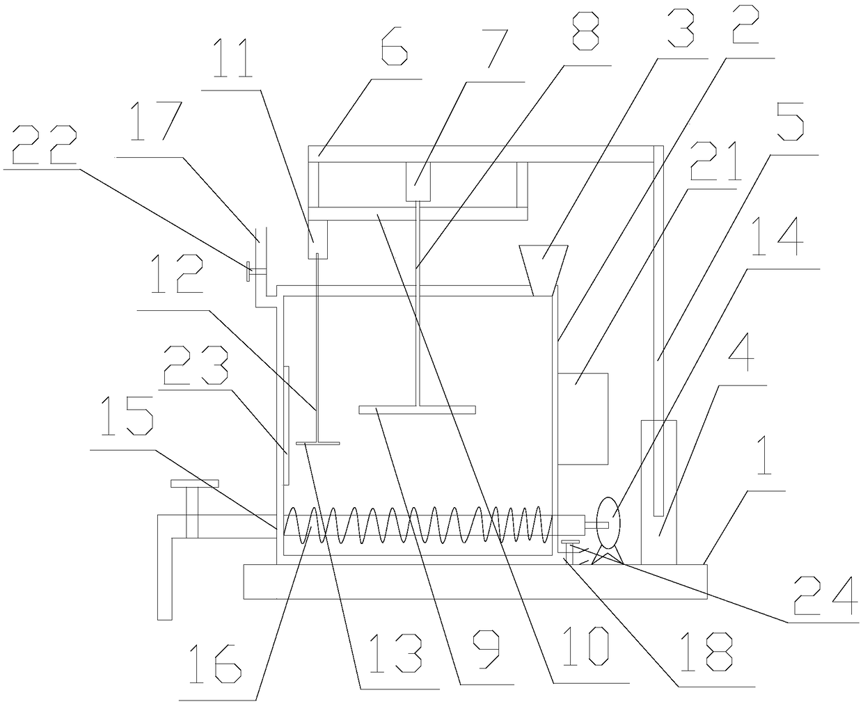
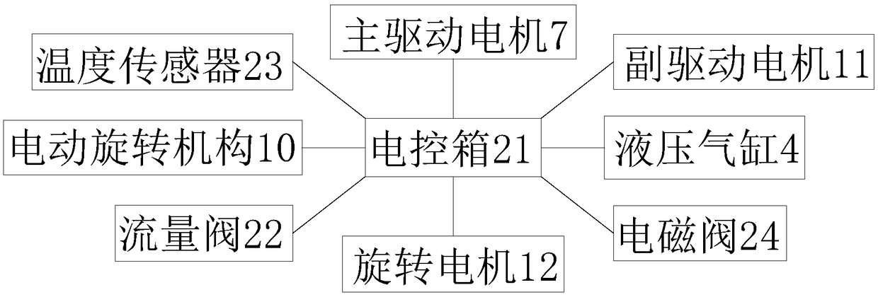
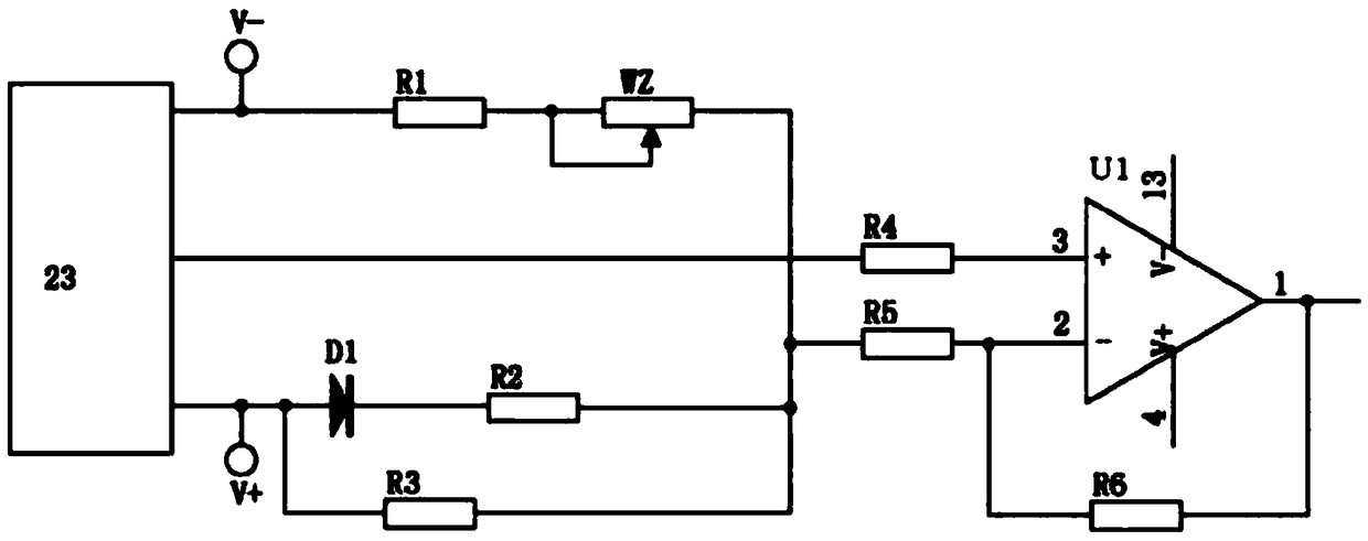
[0023] like Figure 1-3 As shown, the self-controlled cement mixing equipment based on the electric control box provided by the present invention has simple structure, reasonable design, convenient use, can control the mixing temperature in the mixing box, and expands the scope of application. The present invention includes a base 1 fixed on the base 1, a mixing box 2 with a feeding funnel 3 connected to the top, and a double-layer structure, located on one side of the mixing box 2 and fixed on the base 1, with a vertical piston rod 5 The hydraulic cylinder 4 is vertically connected with the vertical piston rod 5 and is positioned at the support rod 6 directly above the mixing box 2, and the main drive motor 7 fixedly connected with the support rod 6 is located in the mixing box 2 and is connected to the drive motor through the main stirring shaft 8. 7. The main stirring blade 9 connected to the drive shaft, located directly below the support rod 6, the electric rotating mecha...


PUM


Abstract

The invention discloses an automatically-controlled cement mixing device based on an electric cabinet. The automatically-controlled cement mixing device overcomes problems in stirring of materials with special requirements on temperature in the prior art. The automatically-controlled cement mixing device comprises a base, an agitator tank, a feeding funnel, a hydraulic cylinder, a vertical pistonrod, a support rod, a main driving motor, a main agitating shaft, main agitating vanes, an electric rotating mechanism, an auxiliary driving motor, an auxiliary agitating shaft, auxiliary agitating vanes, a rotary motor, a discharging port and a lead screw, wherein the agitator tank is fixed on the base, the top of the agitator tank communicates with the feeding funnel, and the outer shell of theagitator tank is of a two-layer structure; an outer shell interlayer located at the top of the agitator tank is provided with a feed inlet pipe connected with an external fluid heat source; and an outer shell interlayer located at the top of the agitator tank is provided with a liquid outlet pipe. A control system comprises the electric control box, a flow valve, a temperature sensor and a solenoid valve, wherein a temperature compensation circuit is connected with the temperature sensor. The automatically-controlled cement mixing device of the invention has the advantages of simple structure,scientific and reasonable design, convenient use, a wide application range and more precise temperature control.

Description

technical field [0001] The invention relates to self-control cement mixing equipment based on an electric control box. Background technique [0002] There are many cement mixing devices for construction, which are generally the mixing chamber and the stirring rod in the chamber body. The stirring rod is equipped with blades, but this kind of stirring device has defects. The length of the stirring rod is fixed, and the position of the blade on it is also fixed, so it can only be used Fully stir the position where the blade is located, and the stirring is insufficient in other places. In addition, the position of the blade is fixed and cannot move up and down in the mixing chamber. Stirring at various heights of the chamber body will easily make the mixing of the stirred items uneven and insufficient. Also have, the size of blade is limited, and blade is too big, and central position is stirred insufficiently, and if blade is too small, the stirring of all around is not enough...

Claims


Application Information

Patent Timeline
Patent Type & Authority Applications(China)
IPC IPC(8): B28C5/16B28C5/08B28C7/02B28C7/16
CPCB28C5/16B28C5/0806B28C5/0831B28C5/0862B28C7/02B28C7/167
Inventor 李健
Owner 四川双利新材料有限公司
Why Eureka
Try Eureka