
Broadband waveguide slotted-type low-axis ratio circularly-polarized antenna for high power microwave measurement

A technology of high-power microwave and circularly polarized antennas, applied in waveguide openings, radiation element structures, circuits, etc., can solve problems such as low power capacity, narrow bandwidth, and low measurement accuracy of high-power microwave radiation fields, and reach the application range wide effect

Inactive Publication Date: 2018-11-27
63653 FORCES PLA
View PDF5 Cites 4 Cited by
  • Summary
  • Abstract
  • Description
  • Claims
  • Application Information

AI Technical Summary

Problems solved by technology

[0005] The invention provides a low-axis-ratio circularly polarized antenna with broadband waveguide slot for high-power microwave measurement, which mainly solves the problems of easy polarization mismatch of conventional linearly polarized receiving antennas and relatively large axis and narrow bandwidth of circularly polarized receiving antennas. , low power capacity and other defects cause low measurement accuracy of high-power microwave radiation field

Method used


Image

  • Broadband waveguide slotted-type low-axis ratio circularly-polarized antenna for high power microwave measurement
  • Broadband waveguide slotted-type low-axis ratio circularly-polarized antenna for high power microwave measurement
  • Broadband waveguide slotted-type low-axis ratio circularly-polarized antenna for high power microwave measurement

Examples


Embodiment 1

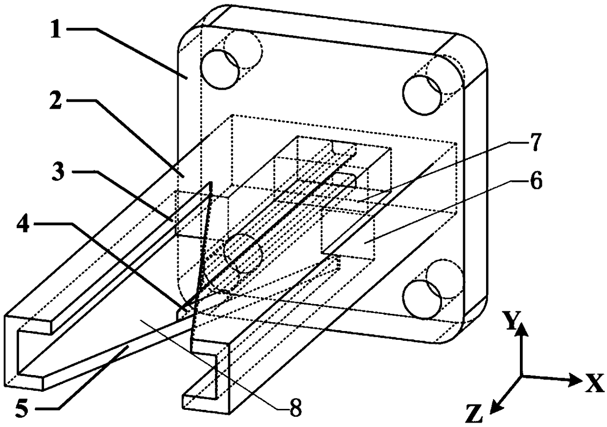
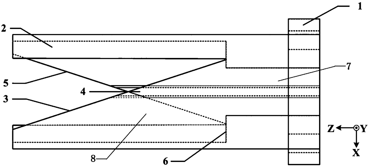
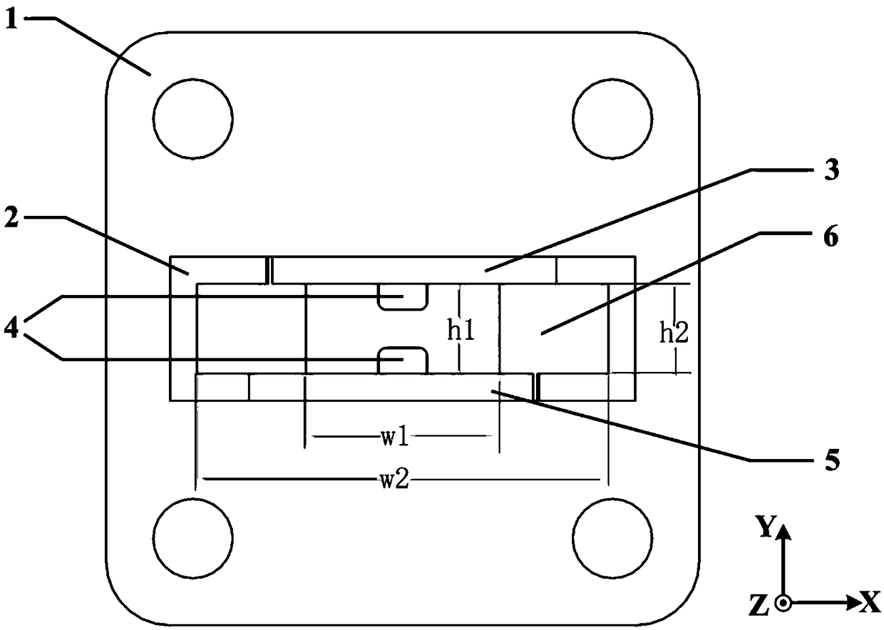
[0028] Grooves are made on both broadside faces of the ridged open waveguide. The dimensions of the two trapezoidal grooves are the same, and they are symmetrical about the central axis of the transmission direction (Z direction) of the open waveguide. By adjusting the size and relative position of the two trapezoidal slots, two orthogonal linear polarizations and a 90° phase delay required for generating circular polarization are provided.

[0029] The interior of the ridged opening waveguide is divided into a linear polarization signal transmission section 7 and a circular polarization signal formation section 8 . The linear polarization signal transmission section is used for linear polarization signal transmission. Standard waveguide structure and size can be selected, and non-standard waveguide design can also be optimized according to frequency band requirements. Generally, the waveguide frequency is mainly affected by the length and width of the mouth surface, and the ...

Embodiment 2

[0047] Grooves are made on both broadside faces of the ridged open waveguide. Depending on the bandwidth, a V-groove can also be selected. The two V-grooves have the same size and are in a symmetrical relationship with the central axis of the transmission direction (Z direction) of the open waveguide. Other structures are all the same as in Example 1.


PUM


Abstract

The invention discloses a broadband waveguide slotted-type low-axis ratio circularly-polarized antenna for high power microwave measurement, which comprises an open-ended waveguide provided with a mounting flange. The open-ended waveguide comprises a waveguide body; the inner part of the waveguide body is divided to two sections of stepped cavities by an interface; the two sections of cavities arerespectively a linearly-polarized signal transmission section and a circularly-polarized signal forming section; two opposite surfaces of the waveguide body are provided with notch grooves; the two notch grooves are centrally symmetrical with the central axis of the open-ended waveguide transmission direction to provide to generate two orthogonal linear polarization and 90-degree phase delay needed by the circularly-polarized signals; and the bottom part of the notch groove is flush with the interface. The problem of low measurement accuracy of a high power microwave radiation field caused bydefects that the conventional linearly-polarized receiving antenna is likely to polarization mismatch and the circularly-polarized receiving antenna is large in axis, narrow in bandwidth and low in power capacity can be mainly solved.

Description

technical field [0001] The invention relates to the technical field of high-power microwave measurement, in particular to a broadband waveguide slotted low-axis-ratio circularly polarized antenna for high-power microwave measurement, which is suitable for high Power microwave measurements. Background technique [0002] High-power microwave refers to strong electromagnetic radiation with a frequency range from 300MHz to 300GHz and a peak power greater than 100MW or an average power greater than 1MW. High-power microwaves have important applications in communication, radar, material processing, nuclear fusion heating and other fields. [0003] Radiation field measurement using antennas is an important means to evaluate the technical indicators of high-power microwave systems. Radiation field power has always been a technical problem. At present, the linearly polarized antenna is usually used as the measuring receiving antenna, and the polarization deflection angle of the li...

Claims


Application Information

Patent Timeline
IPC IPC(8): H01Q13/06H01Q1/36
CPCH01Q1/36H01Q13/06
Inventor 景洪宁辉郝文析陈鹏
Owner 63653 FORCES PLA
Learn More