
Multi-frequency band ultra wideband microstrip antenna

A microstrip antenna and ultra-wideband technology, which is applied in the direction of antenna, antenna grounding device, antenna grounding switch structure connection, etc., can solve the problems of single application environment of microstrip antenna and difficulty in designing microstrip antenna, so as to increase the application value environment and miniaturization

Inactive Publication Date: 2018-11-27
SHANDONG UNIV
View PDF3 Cites 2 Cited by
  • Summary
  • Abstract
  • Description
  • Claims
  • Application Information

AI Technical Summary

Problems solved by technology

[0003] Traditional or existing microstrip antennas are difficult to design microstrip antennas with multiple resonant frequencies and ultra-wide frequency bands due to limitations in structure or electrical performance, and the application environment of existing microstrip antennas is relatively single

Method used


Image

  • Multi-frequency band ultra wideband microstrip antenna
  • Multi-frequency band ultra wideband microstrip antenna
  • Multi-frequency band ultra wideband microstrip antenna

Examples


Embodiment 1

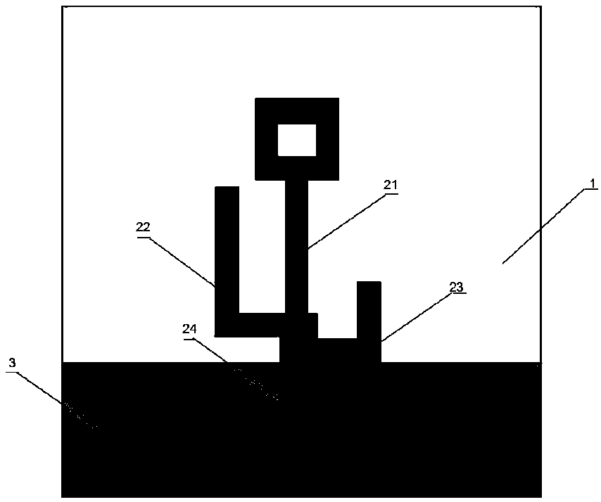
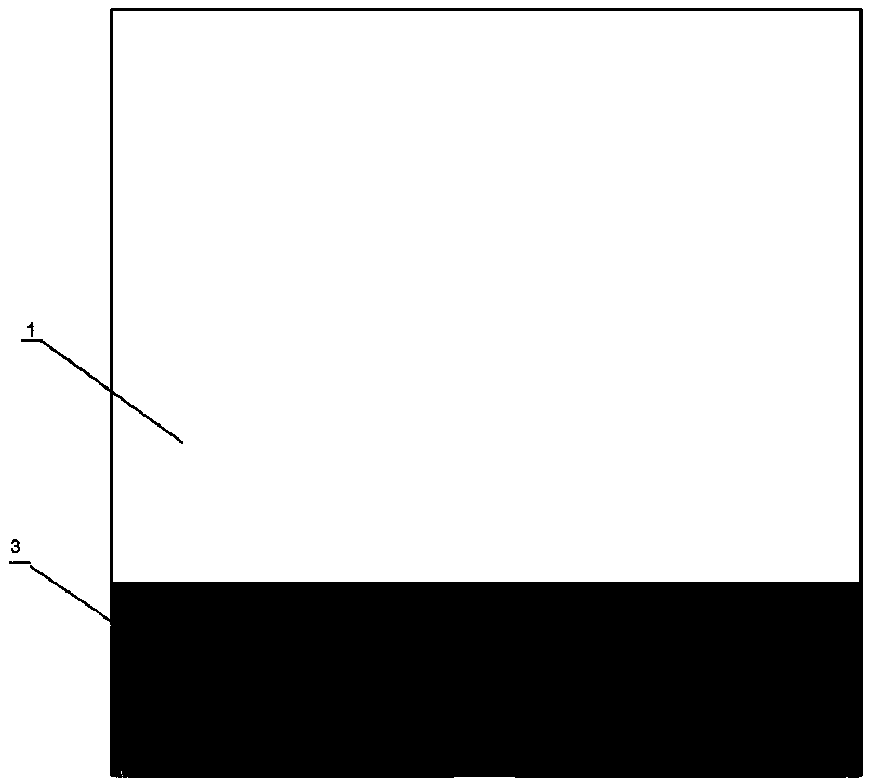
[0029] Such as Figure 1-3 shown.

[0030] A multi-band ultra-broadband microstrip antenna, comprising a dielectric layer 1, one side of the dielectric layer 1 is provided with a radiation patch and a microstrip feeder 24 connected to the radiation patch, and the other side of the dielectric layer 1 is provided with a ground plate 3; the radiation patch includes a middle radiation arm 21 and L-shaped radiation arms arranged on the left and right sides of the middle radiation arm 21; the middle radiation arm 21 includes a rectangular patch and a rectangular ring connected to each other; the L-shaped radiation The arms include a transverse arm and a longitudinal arm; the middle radiating arm 21 and two L-shaped radiating arms generate a resonant frequency respectively; the lower side of the right L-shaped radiating arm transverse 23 coincides with the upper side of the grounding plate 3; The lower side of the transverse arm of the side L-shaped radiating arm 22 coincides with t...

Embodiment 2

[0034] For the multi-band ultra-broadband microstrip antenna described in Embodiment 1, further, the length of the longitudinal arm of the L-shaped radiation arm is greater than the length of the transverse arm.

Embodiment 3

[0036] As in the multi-band ultra-broadband microstrip antenna described in Embodiment 1, further, the central axes of the middle radiation arm 21 and the microstrip feeder 24 coincide in the length direction. Here, the structural design realizes that the radiation corresponding to the resonant frequency generated by the middle radiation arm 21 is omnidirectional radiation.


PUM

PropertyMeasurementUnit
Lengthaaaaaaaaaa
Widthaaaaaaaaaa
Lengthaaaaaaaaaa

Abstract

The invention relates to a multi-frequency band ultra wideband microstrip antenna, which comprises a dielectric layer, wherein a radiation patch and a microstrip feeder line connected with the radiation patch are arranged at one side of the dielectric layer; a grounding plate is arranged at the other side of the dielectric layer; the radiation patch comprises a middle radiation arm and L-shaped radiation arms arranged at the left and right sides of the middle radiation arm; the middle radiation arm comprises a rectangular patch and a rectangular ring in mutual connection; the L-shaped radiation arms comprises a transverse arm and a longitudinal arm; each of the middle radiation arm and the two L-shaped radiation arms generates resonant frequency; the lower side edge of the transverse arm of the L-shaped radiation arm at the right side and the upper side edge of the grounding plate are coincident; the lower side edge of the transverse arm of the L-shaped radiation arm at the left side is coincident with the upper side edge of the transverse arm of the L-shaped radiation arm at the right side.

Description

technical field [0001] The invention relates to a multi-band ultra-wideband microstrip antenna, belonging to the technical field of microstrip antennas. Background technique [0002] Microstrip antennas are widely used in various fields because of their small size, light weight, simple manufacturing process, low profile, and easy conformal realization. With the rapid development of Internet of Things technology and wireless communication technology, more and more wireless frequency bands have been formulated, which requires antennas to be able to work in more frequency bands. At the same time, UWB communication technology, as a new type of wireless communication technology, has outstanding performances such as high-speed data transmission and strong anti-interference ability, and has been widely researched and applied. As the key technology of ultra-wideband communication, the design and research of ultra-wideband antennas has always been a hot spot in the field of antenna ...

Claims


Application Information

Patent Timeline
IPC IPC(8): H01Q1/38H01Q1/48H01Q1/50H01Q5/10H01Q5/28
CPCH01Q1/38H01Q1/48H01Q1/50H01Q5/10H01Q5/28
Inventor 孔繁敏王士铨
Owner SHANDONG UNIV
Learn More