
Robot joint moment balancing device

A robot joint and torque balance technology, which is applied in manipulators, program-controlled manipulators, manufacturing tools, etc., can solve the problems of lossy drive motor and reducer life, brake failure, and potential safety hazards, and achieve compact structure and torque balance , the effect of taking up little space

Active Publication Date: 2018-11-27
ANHUI UNIVERSITY OF TECHNOLOGY AND SCIENCE
View PDF6 Cites 7 Cited by
  • Summary
  • Abstract
  • Description
  • Claims
  • Application Information

AI Technical Summary

Problems solved by technology

[0004] 1. During the operation of the robot arm, the angle between the robot arm and the horizontal plane is constantly changing, resulting in constant changes in the resultant torque generated by the weight of the robot arm and the gravity of the objects being lifted, which brings constant changes to the drive motor and reducer. Load impact, damage the life of the drive motor and reducer;
[0005] 2. During the operation of the robot arm, if the electrical system fails, the brake will fail, and the robot arm and its heavy objects will swing freely under the action of gravity after losing the brake force, posing a safety hazard;
[0006] 3. In the teaching and programming operation of industrial robots, sometimes it is necessary to manually guide the end effector of the robot (the gripper, tool, welding torch, spray gun, etc. installed at the end of the robot's joint structure) to make the robot complete the expected action. Now In some structures, the operator needs to spend a lot of physical strength to pull or push the robot arm to realize the teaching and programming function, which is very inconvenient

Method used


Image

  • Robot joint moment balancing device
  • Robot joint moment balancing device
  • Robot joint moment balancing device

Examples


Embodiment Construction

[0025] Through the description of the embodiments below, the specific implementation of the present invention includes the shape, structure, mutual position and connection relationship between the various parts, the function and working principle of each part, the manufacturing process and the operation and use method of the various components involved. etc., to make further detailed descriptions to help those skilled in the art have a more complete, accurate and in-depth understanding of the inventive concepts and technical solutions of the present invention.

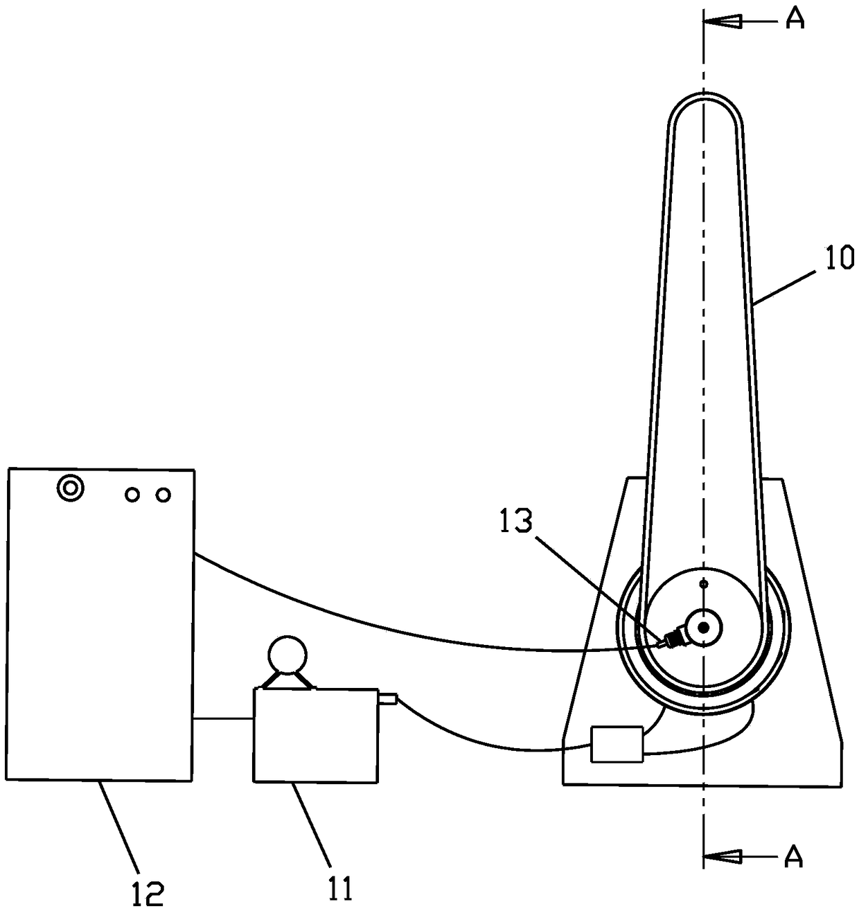
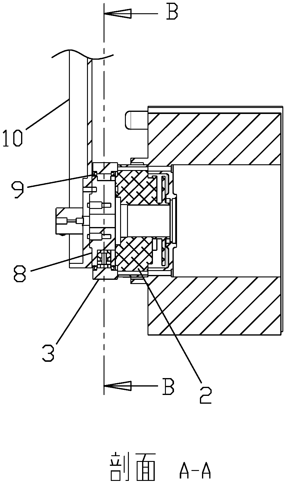
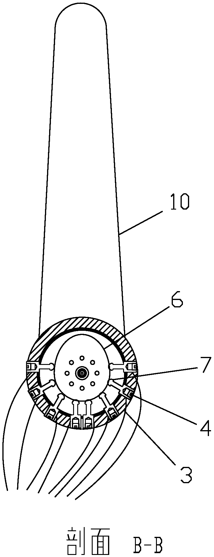
[0026] Such as Figure 1 to Figure 5 As shown, a robot joint torque balance device includes an eccentric cam 6, the central axis of the eccentric cam 6 is fixedly connected to the output end of the RV reducer 2, the robot arm 10 is fixed on the eccentric cam 6, and the symmetric axis of the eccentric cam 6 There is a fixed angle with the centerline of the robot arm 10, preferably 0° or 180°. The eccentric cam 6 is pro...


PUM


Abstract

The invention discloses a robot joint moment balancing device. The robot joint moment balancing device comprises an eccentric cam, a plurality of balance oil cylinders, a hydraulic oil pump, an angleencoder and a PLC, wherein the central shaft of the eccentric cam is fixedly connected with the output end of a RV speed reducer; a robot arm is fixed on the eccentric cam; the balance oil cylinders are arranged on the two sides of the eccentric cam in an axisymmetric manner along the symmetric axis of the eccentric cam; the movable ends of the balance oil cylinders are abutted to the outer contour of the eccentric cam; the hydraulic oil pump is connected with the balance oil cylinders through oil delivering pipelines, and is used for driving the balance oil cylinders to act; the angle encoderis used for detecting angle signals of the eccentric cam or the robot arm; and the PLC is used for receiving angle signals transmitted by the angle encoder, and controlling the hydraulic oil pump toact. The robot joint moment balancing device has the effects that the structure is compact, the occupied space is small, equilibrant moment can be adjusted freely, and dynamically changes along with change of a rotating angle of a big arm, and moment equilibrium in a total working range can be realized.

Description

technical field [0001] The invention relates to the technical field of 6-axis series industrial robots, in particular to a gravity moment balance device for series robot joints, more specifically a robot joint moment balance device. Background technique [0002] The joint parts of industrial robots, especially 6-axis series industrial robots, are mainly drive motors and RV reducers. The arm is fixedly connected. When in use, the control system of the robot sends instructions to the drive motor, which drives the motor to run, and drives the robot arm and the fixed target object on the robot arm to move through the reducer. In the prior art, in order to fix the robot arm at the target position, the robot arm is mainly fixed by installing a holding brake on the side of the driving motor, and then fixing the output shaft of the driving motor through the holding brake. [0003] But there are many problems in this way: [0004] 1. During the operation of the robot arm, the angle...

Claims


Application Information

Patent Timeline
IPC IPC(8): B25J19/00B25J9/12
CPCB25J9/109B25J9/126B25J19/0012
Inventor 方明梁艺刘玉飞吴路路钟相强
Owner ANHUI UNIVERSITY OF TECHNOLOGY AND SCIENCE
Learn More