Chamfer device for annular fastening member

A chamfering device and ring fastening technology, which is applied in positioning devices, clamping, metal processing machinery parts, etc., can solve the problems of short service life of knives, high maintenance costs, failures, etc., so as to prolong the service life and save labor costs , Improve the effect of chamfering accuracy

Inactive Publication Date: 2018-11-27
嘉善信道五金塑料模具厂
View PDF7 Cites 5 Cited by
  • Summary
  • Abstract
  • Description
  • Claims
  • Application Information

AI Technical Summary

Problems solved by technology

These chamfers have many functions, and must be carefully checked and fully utilized during maintenance operations, otherwise it will bring many difficulties to the maintenance of agricultural machinery, and even cause unexpected failures
For example, before the forming process of small parts such as bolts, chamfering is also performed, so that the material can easily enter the forming mold; while the existing chamfering devices are all for processing objects with ordinary shapes, it is not easy to clamp ring fasteners Tight; the knife on the existing chamfering device has a short service life, which increases the maintenance cost during the replacement process

Method used


Image

  • Chamfer device for annular fastening member
  • Chamfer device for annular fastening member
  • Chamfer device for annular fastening member

Examples


Embodiment Construction

[0029] In order to make it easy to understand the technical means, creative features, objectives and effects achieved by the present invention, the present invention will be further explained below in conjunction with the drawings and specific embodiments.

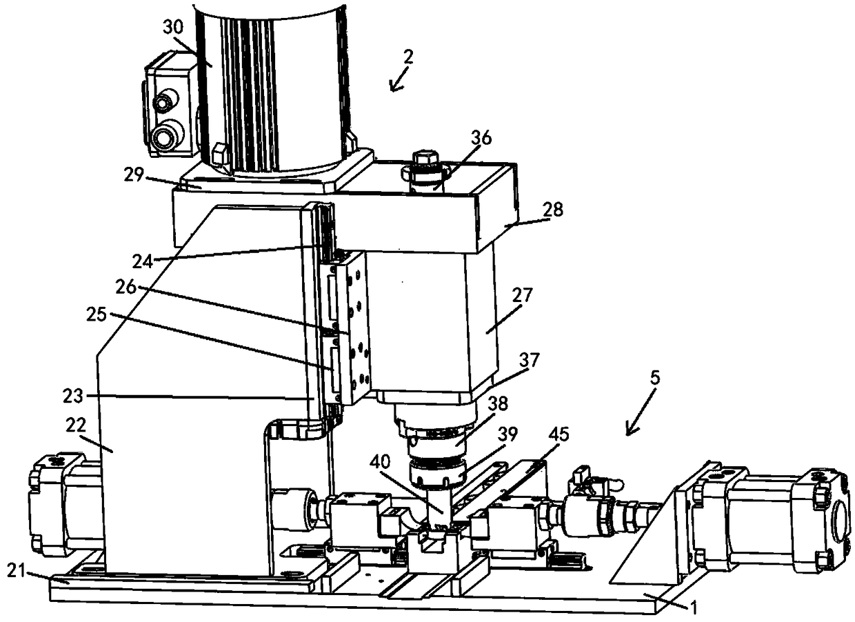
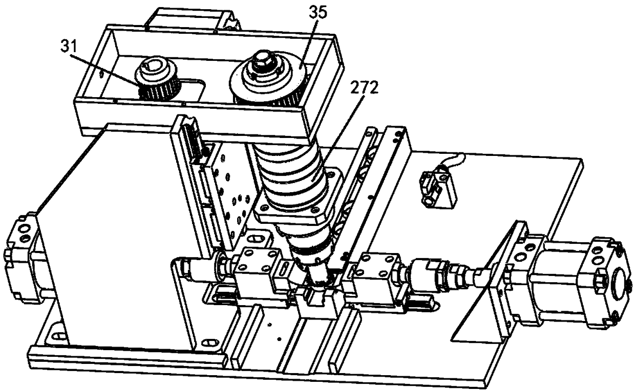
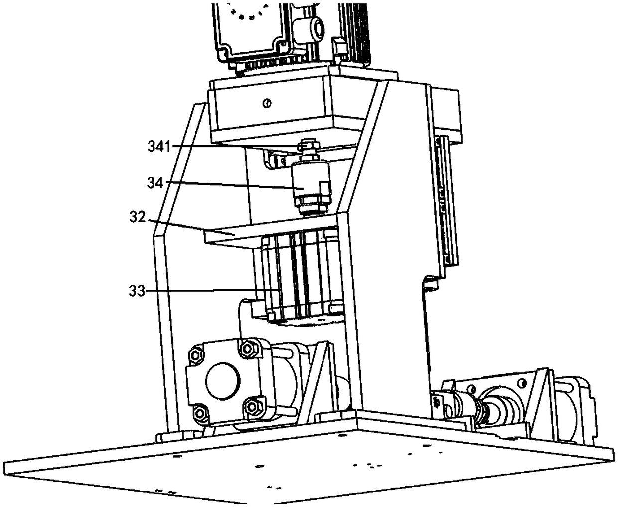
[0030] Such as Figure 1 to Figure 9 As shown, a chamfering device for ring fasteners proposed by the present invention includes a bottom plate 1; the bottom plate 1 is equipped with a chamfering mechanism 2; the chamfering mechanism 2 includes a first fixed on the bottom plate 2. The bottom plate 21, the first bottom plate 21 is fixed with two side vertical plates 22 perpendicular to the first bottom plate 21; the right side end faces of the two side vertical plates 22 are inherently fixed plate 23; the right side of the fixed plate 23 Two first sliding rails 24 are fixed on the side surface, two first sliding blocks 25 are slidably provided on the two first sliding rails 24, and the inherent sliding plate 26 on the right si...


PUM


Abstract

The invention discloses a chamfer device for an annular fastening member. The device comprises a bottom plate, a chamfer mechanism is installed on the bottom plate, the chamfer mechanism comprises a first bottom plate which is fixed to the bottom plate, two side upright plates which are perpendicular to the first bottom plate are fixed to the first bottom plate, fixing plates are fixed to the right side end faces of the two side upright plates, two first sliding rails are fixed to the right side faces of the fixing plates, two first sliding blocks are slidably arranged on the two first slidingrails respectively, sliding plates are fixedly arranged on the right sides of the first sliding blocks, connecting columns are fixedly arranged on the right side faces of the sliding plates, an installing seat is fixedly arranged on the upper end faces of the connecting columns through bolts, the right end of the installing seat is located on the upper end of the connecting columns, the left endof the installing seat penetrates through the fixing plate and extends to the part between the two side upright plates, an installing plate is fixedly arranged at the upper end of the left side of theinstalling seat, a first motor is fixedly arranged on the upper end surface of the installing plate, the output shaft of the first motor penetrates through the installing plate and extends to the interior of the installing seat, and the output shaft of the first motor is fixedly provided with a driving wheel.

Description

Technical field [0001] The invention relates to the field of mechanical processing, in particular to a chamfering device for ring fasteners. Background technique [0002] On agricultural machinery parts, especially round parts and round holes, the end faces are often processed into a chamfer of about 45°. These chamfers have many functions. They must be checked carefully and fully utilized during maintenance operations. Otherwise, it will bring many difficulties to the maintenance of agricultural machinery and even cause unexpected failures. For example, before the forming process of small parts such as bolts, chamfering is also carried out, so that the material can easily enter the forming mold; and the existing chamfering devices are used to process objects of ordinary shapes, and it is not easy to clamp the ring fasteners. Tight; the use cycle of the knife on the existing chamfering device is short, which increases the maintenance cost during the replacement process. [0003] ...

Claims


Application Information

Patent Timeline
Patent Type & Authority Applications(China)
IPC IPC(8): B23Q3/08B23D79/00B23D79/04
CPCB23Q3/08B23D79/00B23D79/04
Inventor 张春梦
Owner 嘉善信道五金塑料模具厂
Why Eureka
Try Eureka