
Synchronous Control Method of Multiple Groups of tdi CMOS Imaging System

A technology of synchronous control and imaging system, applied in the parts of TV system, image communication, color TV, etc., can solve the problem of sampling metastability, to ensure robustness, ensure stable and reliable reception, and avoid shooting. The effect of frequency interference

Active Publication Date: 2021-05-04
CHANGCHUN INST OF OPTICS FINE MECHANICS & PHYSICS CHINESE ACAD OF SCI
View PDF6 Cites 0 Cited by
  • Summary
  • Abstract
  • Description
  • Claims
  • Application Information

AI Technical Summary

Problems solved by technology

[0003] The present invention provides a synchronous control method for multiple groups of TDI CMOS imaging systems in order to solve the problem of sampling metastable state existing in the imaging control of the existing imaging system

Method used


Image

  • Synchronous Control Method of Multiple Groups of tdi CMOS Imaging System
  • Synchronous Control Method of Multiple Groups of tdi CMOS Imaging System
  • Synchronous Control Method of Multiple Groups of tdi CMOS Imaging System

Examples


specific Embodiment approach 1

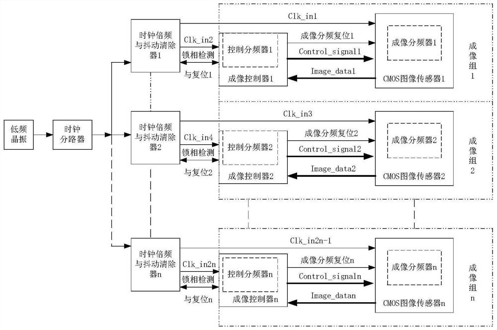
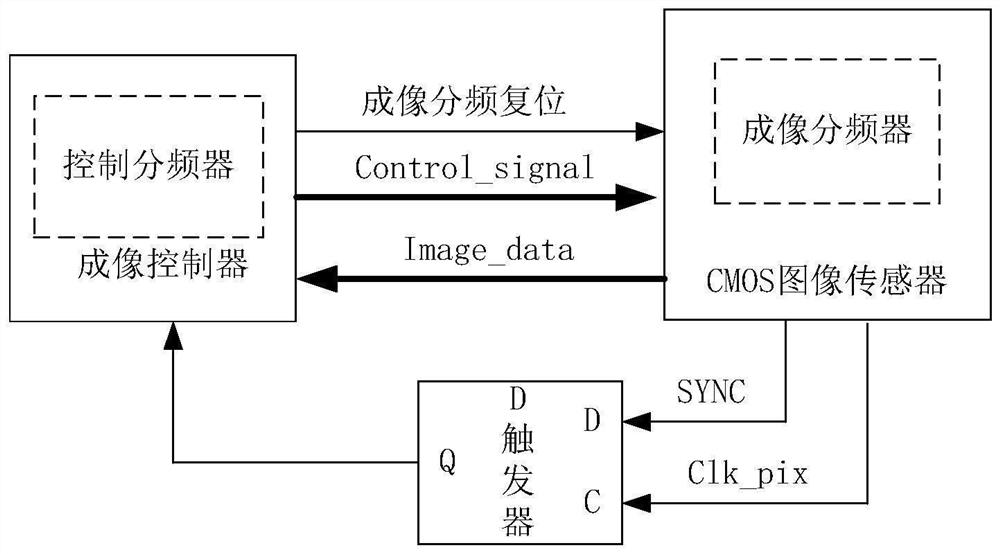
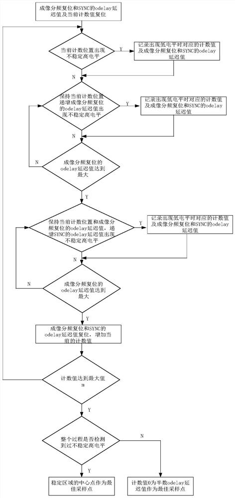
[0020] Specific implementation mode 1. Combination Figure 1 to Figure 3 Describe this embodiment, based on the synchronous control method of multiple groups of TDI CMOS imaging systems for aerospace applications,

[0021] The synchronous control system structure of multiple groups of TDI CMOS imaging is as follows: figure 1 As shown, each imaging group uses the same frequency as The low-frequency clock source is used as the clock reference, and the low-frequency clock is used for transmission; the frequency generated by the low-frequency crystal oscillator is (p is a positive integer greater than 1) the low-frequency clock is divided into n channels after the clock splitter, and the nearest output frequency is f after passing through n clock frequency multipliers and jitter cleaners respectively inter The clock with high frequency and low jitter is sent to n groups of imaging groups to eliminate additional jitter during long-distance transmission. Each imaging group main...


PUM


Abstract

A synchronous control method for multiple groups of TDI CMOS imaging systems relates to a synchronous control method for multiple groups of TDI CMOS imaging systems based on aerospace applications, and solves the problem of sampling metastable states in existing imaging systems during imaging control. The invention uses a single low-frequency The crystal oscillator is sent to each imaging unit through the clock divider and then the external clock frequency multiplier and jitter cleaner respectively; by testing the metastable state area of ​​sampling, by adjusting the rise of the clock divider reset signal edge, so as to ensure the robustness of control signal sampling. The low-frequency clock signal is used for dejittering and frequency multiplication near the imaging controller to avoid the amplitude attenuation and jitter increase of the high-frequency clock, thereby ensuring the stable and reliable reception of high-speed serial data; by testing the metastable area of ​​sampling, by adjusting The clock divider resets the rising edge of the signal, thereby ensuring the robustness of the control signal sampling, and the detector can work stably under various temperature conditions.

Description

technical field [0001] The invention relates to a synchronous control method of a multi-group CMOS imaging system, in particular to a synchronous control method of a multi-group TDI CMOS imaging system based on aerospace applications. Background technique [0002] For multi-group imaging systems, if each part adopts independent clocks for imaging control, there may be beat frequency interference among the imaging systems of each group, resulting in interference fringes on the image; for CMOS imaging systems using high-speed serial data transmission interfaces, for The signal integrity and jitter requirements of high-frequency data clocks are high. In order to avoid the impact of beat frequency, when the same synchronous clock is used for all parts, it is easy to cause high-frequency signals to attenuate the signal amplitude and increase jitter after passing through the transmission cable; CMOS detectors for aerospace applications , The phase-locked loop is canceled in the ch...

Claims


Application Information

Patent Timeline
Patent Type & Authority Patents(China)
IPC IPC(8): H04N5/232H04N5/04H04N5/374
CPCH04N5/04H04N23/682H04N23/683H04N25/76
Inventor 余达刘金国周怀得薛旭成吕宝林姜楠李树军
Owner CHANGCHUN INST OF OPTICS FINE MECHANICS & PHYSICS CHINESE ACAD OF SCI
Learn More