Estimation method for train running state parameter based on time-frequency map processing of optical fiber sensing
A technology of operating status and optical fiber sensing, applied in image data processing, computing, image analysis, etc., can solve problems such as limited number of monitoring points, large environmental impact, complex system, etc.
- Summary
- Abstract
- Description
- Claims
- Application Information
AI Technical Summary
Problems solved by technology
Method used
Image
Examples
Embodiment 1
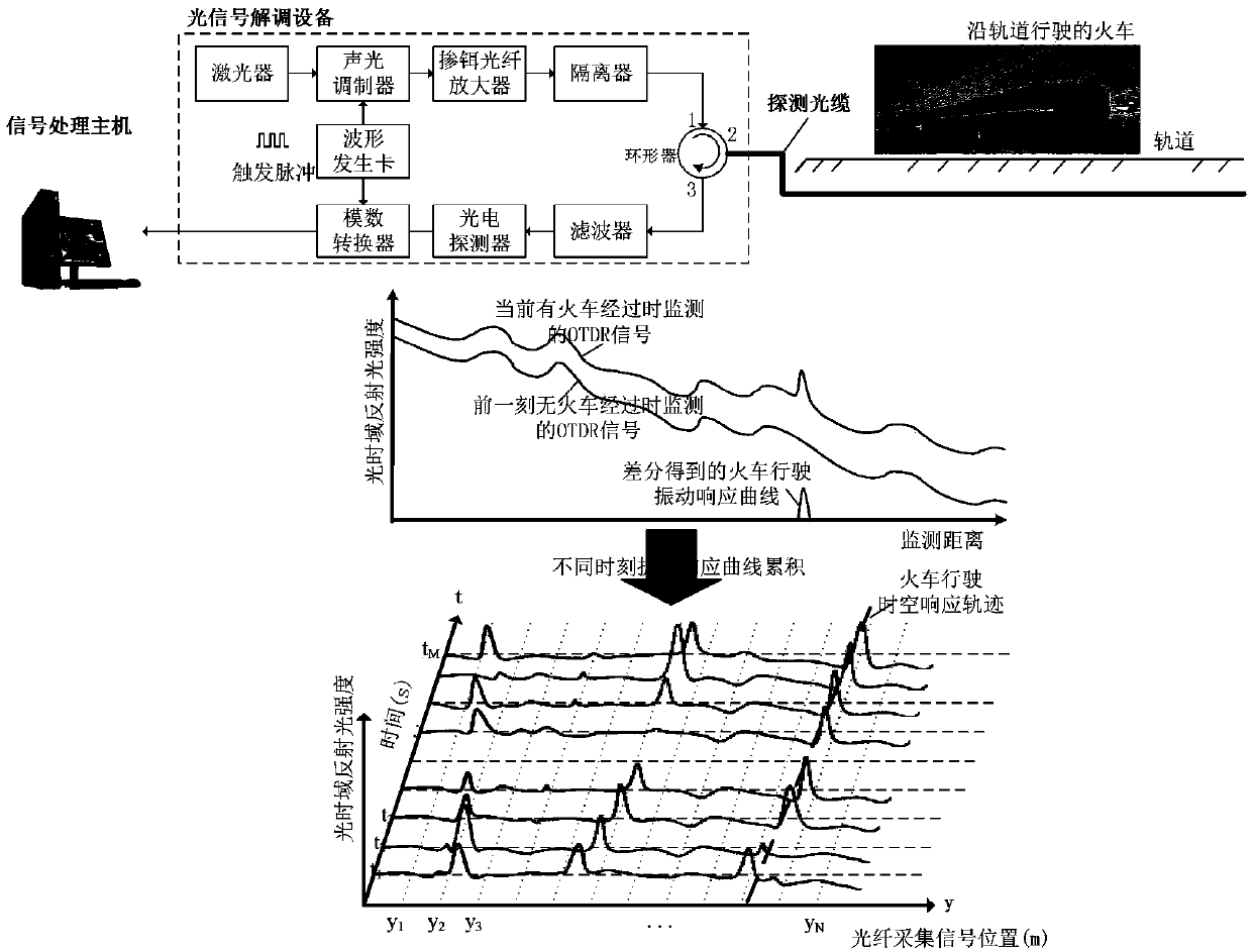
[0065] As a first embodiment, a phase-sensitive optical time-domain reflectometer is used to collect spatio-temporal vibration signals. like figure 1 As shown, one of the spare cores of the ordinary communication optical cable buried along the train track is connected to a phase-sensitive optical time domain reflectometer (Φ-OTDR). Partial composition. The detection optical cable is a single-mode optical fiber for ordinary communication. The optical cable is generally buried along the urban track, parallel to the track or at any angle (except 90°), and senses the ground vibration caused by passing trains on the track to realize the detection of trains near the optical cable. Online monitoring of track safety. Optical signal demodulation equipment is the core of the system. Its internal components mainly include optical devices and electrical devices. An ultra-narrow linewidth laser generates a continuous coherent optical signal, which is modulated into an optical pulse signa...
Embodiment 2
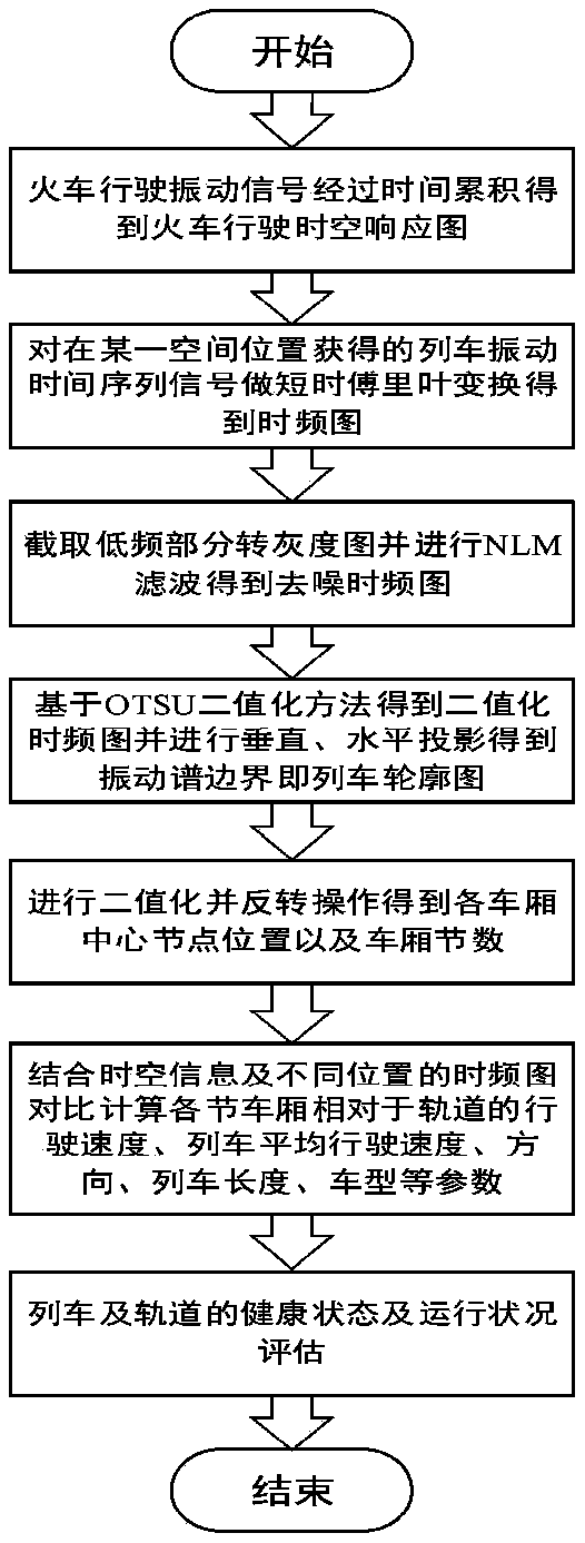
[0067] As the second embodiment, based on the method for estimating the parameters of the train running state based on optical fiber sensing time-frequency image processing, the phase of the pulsed light is demodulated by detecting the change of the interference fringe of Rayleigh scattered light at different times, that is, the optical time domain reflection track (OTDR track). Changes in the train, so as to perceive and locate the vibration caused by the train running, and obtain the time-frequency spectrum of each position from its vibration space-time response graph, and estimate the running state parameters such as the speed, direction and position of the train that generates the vibration signal in real time. Method flow chart as figure 2 As shown, the method steps are:
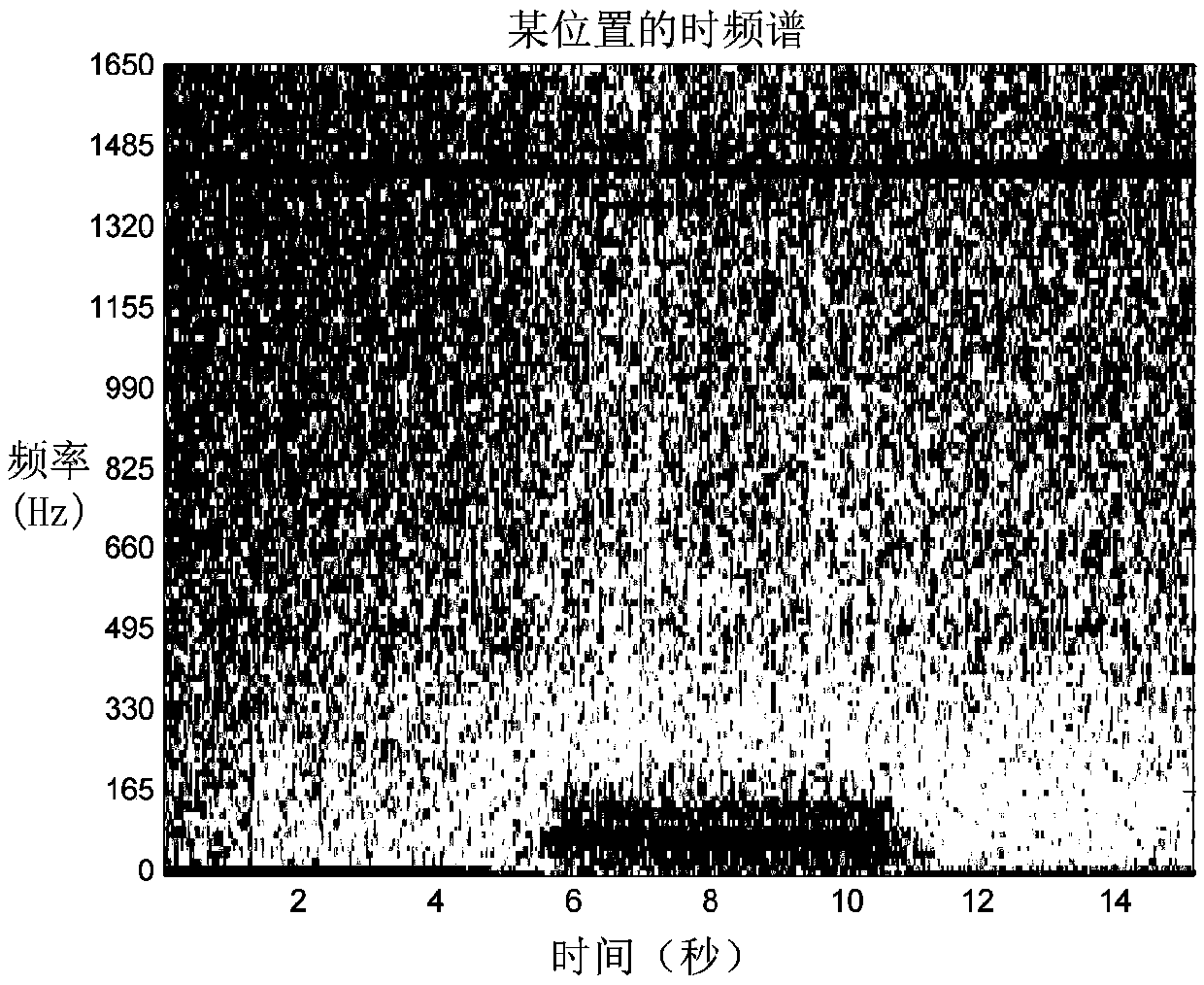
[0068] Step (1), the signal is collected in real time through the optical fiber buried along the train track, and the space-time vibration signal of the train running process along the track is obtaine...
PUM
 Abstract
Description
Claims
Application Information
 - R&D Engineer
- R&D Manager
- IP Professional
- Industry Leading Data Capabilities
- Powerful AI technology
- Patent DNA Extraction
Browse by: Latest US Patents, China's latest patents, Technical Efficacy Thesaurus, Application Domain, Technology Topic, Popular Technical Reports.
© 2024 PatSnap. All rights reserved.Legal|Privacy policy|Modern Slavery Act Transparency Statement|Sitemap|About US| Contact US: help@patsnap.com


