
Display panel and display device

A technology of display panel and display area, which is applied in the fields of instruments, computing, electrical and digital data processing, etc., can solve the problems of large load difference of data signal lines, poor display uniformity of display panel, large load difference, etc.

Active Publication Date: 2018-11-23
SHANGHAI TIANMA MICRO ELECTRONICS CO LTD
View PDF4 Cites 11 Cited by
  • Summary
  • Abstract
  • Description
  • Claims
  • Application Information

AI Technical Summary

Problems solved by technology

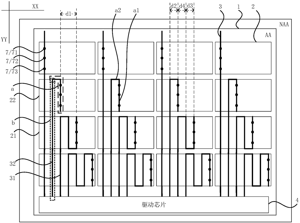
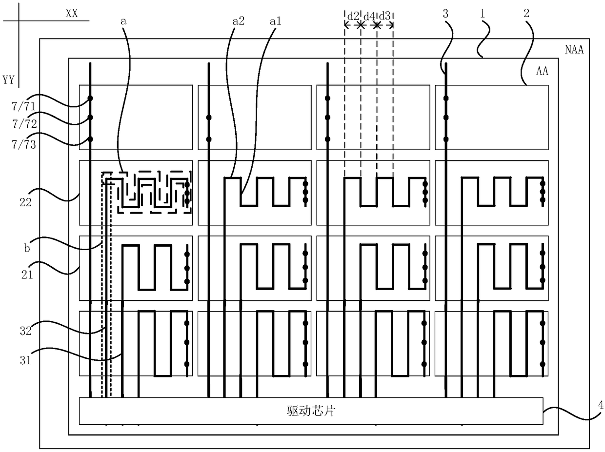
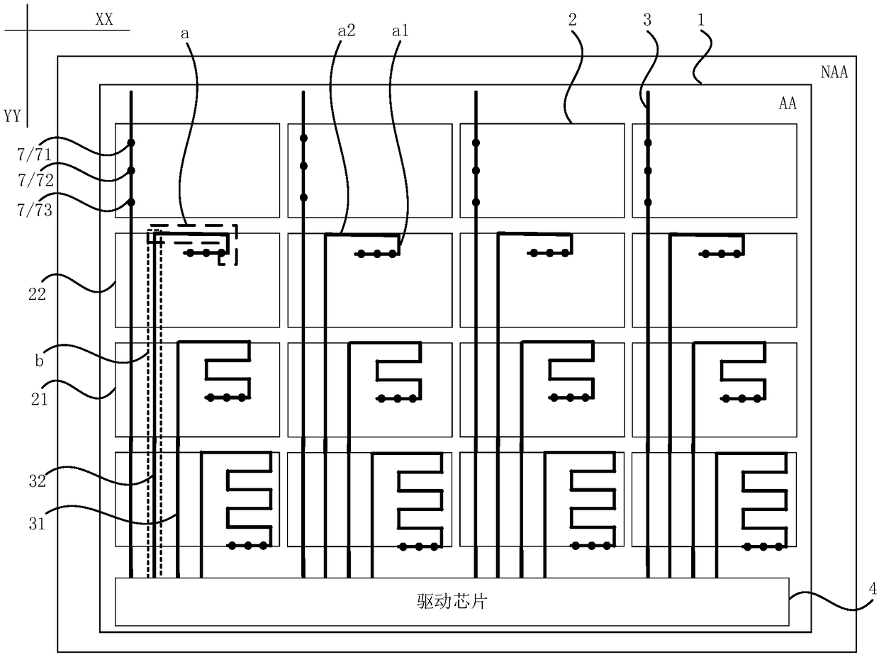
[0003] The total lengths of the touch wires electrically connected to the driver chip from the touch electrodes with different distances from the driver chip are different, so that the loads on the touch wires electrically connected to the touch electrodes with different distances from the driver chip are greatly different. As a result, the touch uniformity of the display panel is poor
In addition, due to the coupling effect between the touch wires and the data signal lines connected to each pixel unit in the display panel, the touch electrodes with different distances from the drive chip are electrically connected to the touch wires with different lengths to the drive chip. It will lead to a large difference in the load on the data signal line electrically connected to the pixel unit with different distances from the driver chip, which will lead to poor display uniformity of the display panel

Method used


Image

  • Display panel and display device
  • Display panel and display device
  • Display panel and display device

Examples


Embodiment Construction

[0025] The present invention will be further described in detail below in conjunction with the accompanying drawings and embodiments. It should be understood that the specific embodiments described here are only used to explain the present invention, but not to limit the present invention. In addition, it should be noted that, for the convenience of description, only some structures related to the present invention are shown in the drawings but not all structures. Throughout this specification, the same or similar reference numerals represent the same or similar structures, elements or processes. It should be noted that, in the case of no conflict, the embodiments in the present application and the features in the embodiments can be combined with each other.

[0026] An embodiment of the present invention provides a display panel. The display panel is divided into a display area and a non-display area surrounding the display area. The display panel includes a first substrate,...


PUM


Abstract

The invention discloses a display panel and a display device. The display panel includes a plurality of touch electrodes, a plurality of touch traces, and a driving chip arranged on a first substrate;at least part of the touch traces include bent portions, and vertical projections of bent portions of touch traces on the first substrate are located in vertical projections of touch electrodes electrically connected to touch traces on the first substrate. The plurality of touch electrodes include a first touch electrode and a second touch electrode, and the distance from the first touch electrode to the driving chip is shorter than the distance from the second touch electrode to the driving chip. The plurality of touch traces include a first touch trace electrically connected to the first touch electrode and a second touch trace electrically connected to the second touch electrode, and the total length of portions of the first touch trace is longer than the total length of bent portionsof the second touch trace. According to the display panel and the display device, the touch uniformity, the display uniformity and the touch accuracy of the display panel are improved.

Description

technical field [0001] Embodiments of the present invention relate to the field of display technology, and in particular, to a display panel and a display device. Background technique [0002] A display panel integrated with a touch function generally includes a plurality of touch electrodes and a plurality of touch wires. The driver chip in the display panel is electrically connected to the corresponding touch electrodes through the touch wires, and the driver chip is Send a touch signal to the corresponding touch electrode, the touch electrode senses the capacitance change value generated by the touch body touching the display panel and generates a corresponding touch sensing signal to feed back to the driver chip, and the driver chip responds according to the received touch sensor The detection signal is used to determine the position where the touch subject touches the display panel. [0003] The total lengths of the touch wires electrically connected to the driver chip...

Claims


Application Information

Patent Timeline
IPC IPC(8): G06F3/041G06F3/044
CPCG06F3/0412G06F3/044
Inventor 戴文君
Owner SHANGHAI TIANMA MICRO ELECTRONICS CO LTD
Learn More