


Quick Research
Generate reliable direction feasibility study reports for your R&D in just a few steps.

Technical Q&A
Discover and master advanced knowledge NOW. Basics, ideas, possibilities, all at once.

Find Solutions
As an expert in R&D theories, this can generate solutions to your technical problems instantly.

Evaluate Feasibility
Analyze your overall solution with one click, know your potential R&D risks in advance.

Monitor Landscape
Get weekly tech updates, stay abreast of the latest tech innovations and key insights.
Additional bending moment vibration damping system for stay cable based on macro fiber composite material
A composite material and additional bending moment technology, which can be applied to controllers with specific characteristics, electric controllers, etc., can solve the problems of unsightly appearance, the vibration reduction effect of auxiliary cables is greatly affected by the environment, etc., to achieve precise adjustment of frequency and easy implementation. , the effect of reducing the amplitude
- Summary
- Abstract
- Description
- Claims
- Application Information
AI Technical Summary
Problems solved by technology
Method used
Image

Examples
Embodiment 1
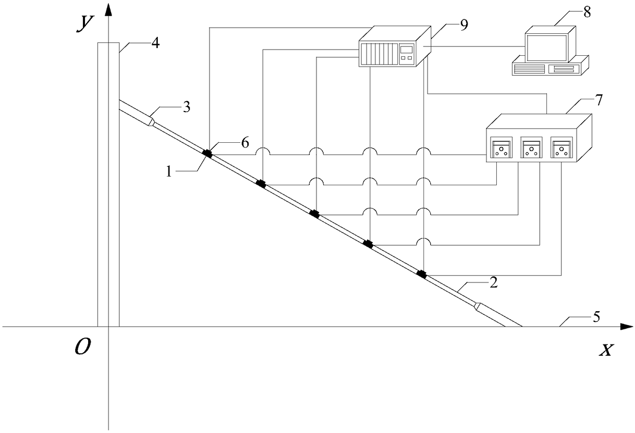
[0052] figure 1 It shows the cable additional bending moment vibration damping system based on MFC, the cable 2 is connected between the bridge tower 4 and the bridge deck 5 through the fixed end 3 of the cable, and the MFC group 1 and the displacement sensor 6 are arranged on the cable 2 , the displacement sensor 6 is connected to the input end of the dSPACE real-time simulation system 9, the output end of the dSPACE real-time simulation system 9 is connected to the input end of the high-voltage amplifier 7, the output end of the high-voltage amplifier 7 is connected to the MFC group 1, and the dSPACE real-time simulation system 9 is connected to the computer 8 .
Embodiment 2
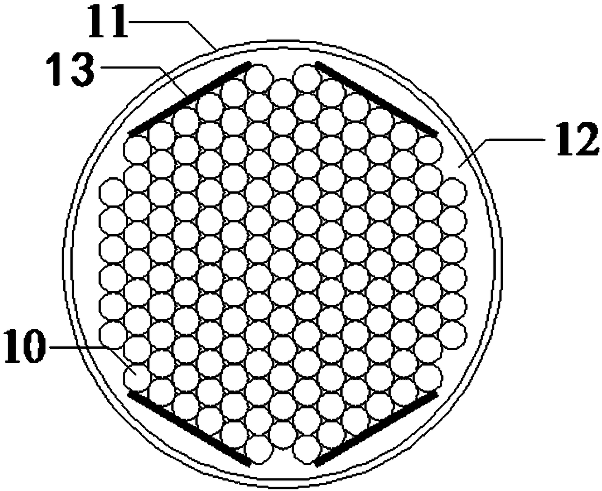
[0054] figure 2 Indicates the horizontal paste position of MFC. Four MFCs 13 are pasted symmetrically in pairs around the steel strands 10 of the cables. A casing 11 is provided outside the steel strands 10 , and a filler 12 is also provided between the steel strands 10 and the sleeves 11 .
Embodiment 3
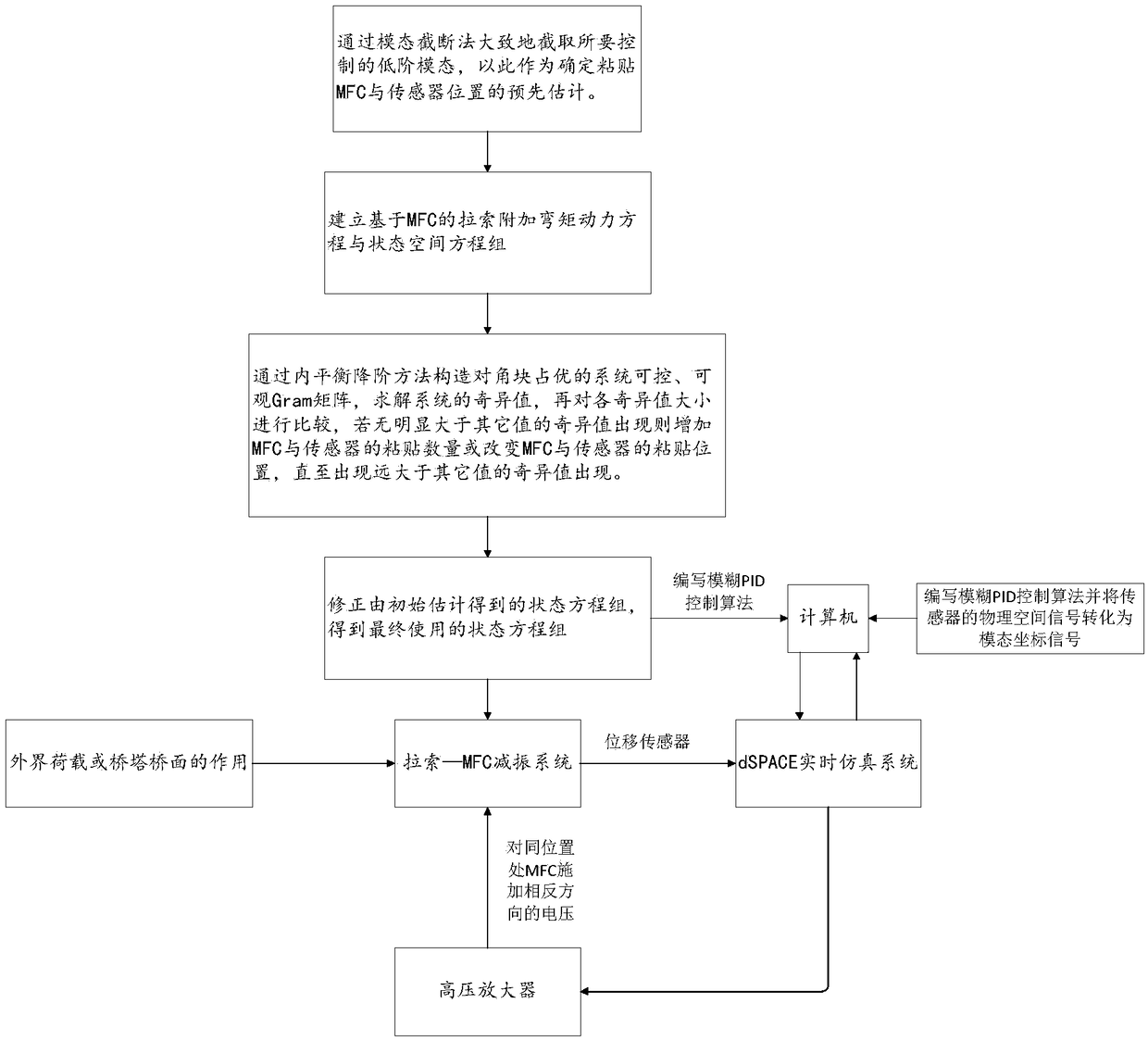
[0056] image 3 It is a schematic flow chart of the cable additional bending moment vibration damping system based on MFC. (1) Firstly, determine the sticking position of the MFC and the sensor. Paste the pre-estimation of the position of the MFC and the sensor; (2) Establish the dynamic equation and the state space equation of the additional bending moment of the cable based on the MFC; (3) Since the cable is a flexible structure with a relatively dense frequency, the internal balance drop First-order method, construct a controllable and observable Gram matrix of the system with diagonal blocks dominant, solve the singular value of the system, compare the size of the singular value, if there is no situation that is obviously larger than other singular values, increase the number of MFC and sensors or change the number of MFC and Paste the position of the sensor until there is a singular value that is much larger than other singular values. Stop, retain the internal equilibriu...
PUM
 Abstract
Description
Claims
Application Information
 - R&D Engineer
- R&D Manager
- IP Professional
- Industry Leading Data Capabilities
- Powerful AI technology
- Patent DNA Extraction
Browse by: Latest US Patents, China's latest patents, Technical Efficacy Thesaurus, Application Domain, Technology Topic, Popular Technical Reports.
© 2024 PatSnap. All rights reserved.Legal|Privacy policy|Modern Slavery Act Transparency Statement|Sitemap|About US| Contact US: help@patsnap.com