A grain sampling device for a grain depot

A technology for sampling and grain, applied in the field of grain-sampling device in grain depots, can solve the problems of small remaining space for grain surface and warehouse roof, unstable grain surface, and inability to cut samples, so as to avoid human hidden dangers and reduce The effect of human participation

Active Publication Date: 2020-07-24
ANHUI JULI MACHINERY MFG +1
View PDF6 Cites 0 Cited by
  • Summary
  • Abstract
  • Description
  • Claims
  • Application Information

AI Technical Summary

Problems solved by technology

[0004] What the present invention aims to overcome is that the grain surface of the cutting machine is not stable, and the remaining space between the grain surface and the roof of the warehouse is small, so that the problem that the cutting machine cannot be cut or the cutting is inaccurate, and the purpose is to provide a grain cutting device for the grain depot

Method used


Image

  • A grain sampling device for a grain depot
  • A grain sampling device for a grain depot
  • A grain sampling device for a grain depot

Examples


Embodiment 1

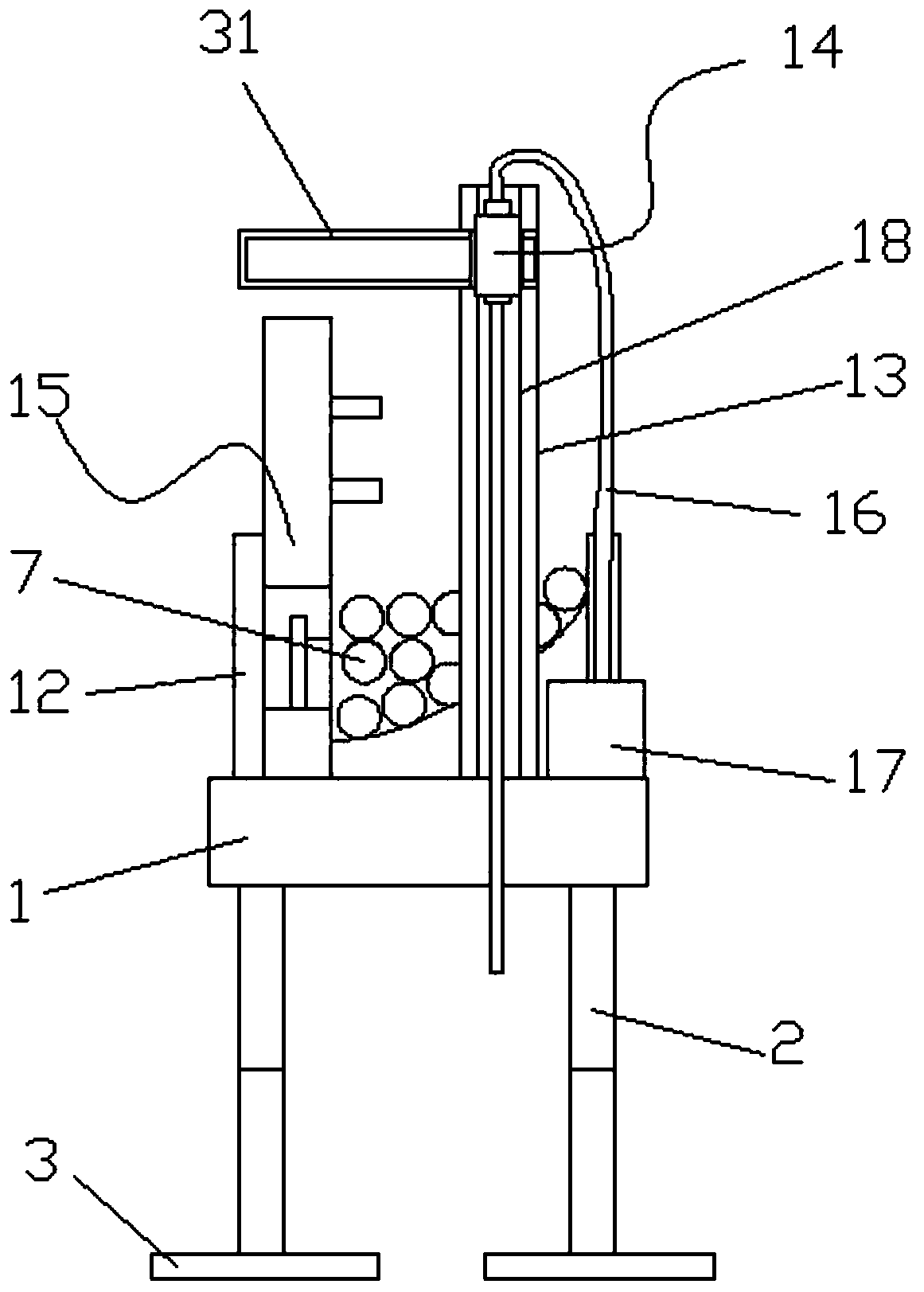
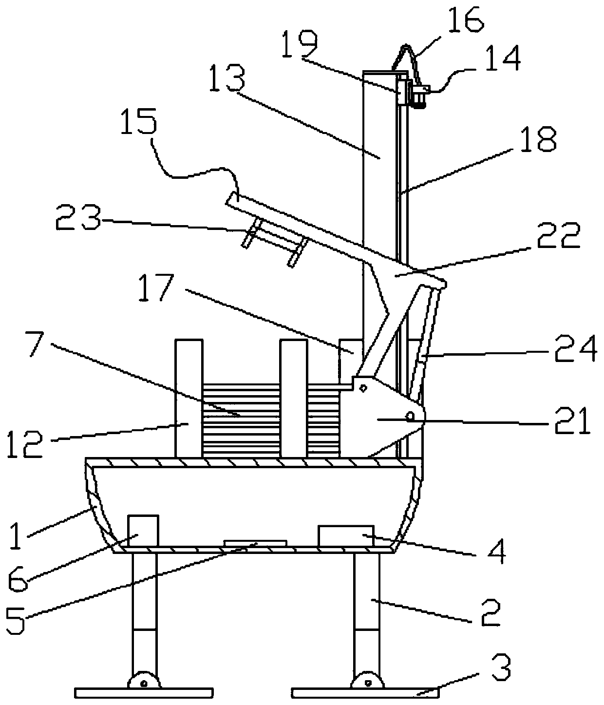
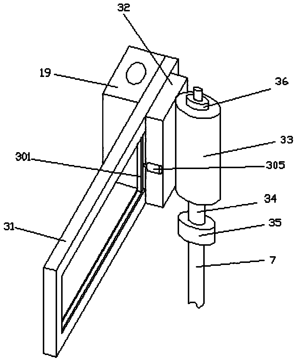
[0028] like figure 1 Shown; A grain depot grain sampling device, comprising a base box 1, a sampling rod 7, four corners of the lower bottom surface of the base box 1 are fixedly installed with four groups of first electric telescopic rods 2 perpendicular to the lower bottom surface, the first The lower end of the electric telescopic rod 2 is hinged with a horizontal backing plate 3, and a controller 4, a level sensor 5 and a battery pack 6 are installed inside the base box 1, and the controller 4 is electrically connected to the level sensor 5 and the first electric telescopic rod 2 and the battery pack. 6. Both sides of the upper surface of the base box 1 are provided with baffles 12, and the sample rod 7 is located on the upper surface of the base box 1 between the baffles 12 on both sides. The front end of the base box 1 is equipped with a column 13 perpendicular to the upper surface. 13 upper end is equipped with inserting rod device 14, and the base box 1 upper surface o...

Embodiment 2

[0032] like figure 1 Shown; A grain depot grain sampling device, comprising a base box 1, a sampling rod 7, four corners of the lower bottom surface of the base box 1 are fixedly installed with four groups of first electric telescopic rods 2 perpendicular to the lower bottom surface, the first The lower end of the electric telescopic rod 2 is hinged with a horizontal backing plate 3, and a controller 4, a level sensor 5 and a battery pack 6 are installed inside the base box 1, and the controller 4 is electrically connected to the level sensor 5 and the first electric telescopic rod 2 and the battery pack. 6. Both sides of the upper surface of the base box 1 are provided with baffles 12, and the sample rod 7 is located on the upper surface of the base box 1 between the baffles 12 on both sides. The front end of the base box 1 is equipped with a column 13 perpendicular to the upper surface. 13 upper end is equipped with inserting rod device 14, and the base box 1 upper surface o...


PUM


Abstract

The invention discloses a grain sampling device for a grain depot, and relates to the technical field of grain sampling machinery. The grain sampling device comprises a base box; four groups of firstelectric telescopic rods perpendicular to the lower bottom surface are fixedly arranged at the four corners of the lower bottom surface of the base box; horizontal base plates are hinged to the lowerends of the first electric telescopic rods; a controller, a level sensor and a storage battery pack are arranged in the base box; baffle plates are arranged on the two sides of the upper surface of the base box; sampling rods are located at the position, between the baffle plates on the two sides, of the upper surface of the base box; stand columns perpendicular to the upper surface are arranged at the front end of the base box; an inserting rod device is arranged at the upper ends of the stand columns, a rod taking device is arranged at the position, on one sides of the stand columns, of theupper surface of the base box; and the upper end of the inserting rod device is connected with a grain sucking device through a hose. The grain sampling device has the advantages that balance self-adjusting can be realized, inclination can be avoided when the sampling rods are inserted, and the grain depot with a relatively high storage capacity can be sampled under the condition that the remaining space between the grain surface and the depot top is small.

Description

technical field [0001] The invention relates to the technical field of grain sampling machinery, in particular to a grain sampling device for a grain depot. Background technique [0002] There is an existing Chinese invention patent, the application number is CN201610150348.8, a multi-functional grain depot intelligent inspection robot, including a crawler walking system, an automatic detection system for grain piles, a leveling system for grain piles, a power supply system, and a camera Monitoring system, wireless signal transmission system and control system; crawler walking system includes chassis and rubber crawler; grain pile automatic detection system includes drilling frame, the upper surface of the drilling frame is horizontally equipped with a mounting plate, and the center of the lower surface of the mounting plate is vertically fixed and connected with a telescopic The telescopic joint is equipped with a drilling device and a sensor detection device, and the middl...

Claims


Application Information

Patent Timeline
Patent Type & Authority Patents(China)
IPC IPC(8): G01N1/14
CPCG01N1/14G01N2001/1418
Inventor 周平曹静吴敏龙凤兰韩小涛许超刘社会朱丙勤唐建飞王志卿
Owner ANHUI JULI MACHINERY MFG
Why Eureka
Try Eureka