
Non-contact three-dimensional automatic scanning testing system

A non-contact, scanning test technology, applied in general control systems, control/adjustment systems, measuring devices, etc., can solve the problems of slow movement and measurement speed, can only be used in laboratories, and cannot measure workpieces, etc., to improve Effects of measurement efficiency, improvement of measurement accuracy, and expansion of measurement range

Inactive Publication Date: 2018-11-23
苏州艾弗伦智能技术有限公司
View PDF7 Cites 5 Cited by
  • Summary
  • Abstract
  • Description
  • Claims
  • Application Information

AI Technical Summary

Problems solved by technology

[0003] Now most of the visual measurement equipment of the manufacturers is fixed by a tripod. This method is relatively slow in movement and measurement speed. Most of them can only be used in the laboratory and cannot be used in the factory online measurement technology.
In factory production, the equipment that needs precision measurement is mostly three-coordinate measuring instrument or visual measurement equipment, but the existing measurement equipment often has the following shortcomings when used: 1. The equipment is affected by the frame and stroke without exception. However, it is impossible to measure workpieces with large size differences; 2. The measuring equipment in the prior art can only measure the size of a single angle of large workpieces, but cannot measure the multi-angle and multi-plane of the workpiece; 3. Perform data processing and online measurement on the measured equipment; 4. The efficiency of equipment operation measurement is low, and fast measurement cannot be performed

Method used


Image

  • Non-contact three-dimensional automatic scanning testing system

Examples


Embodiment Construction

[0018] The following will clearly and completely describe the technical solutions in specific embodiments of the present invention in conjunction with the schematic structural diagrams of the present invention. Apparently, the described embodiments are only some of the embodiments of the present invention, but not all of them. Based on the embodiments of the present invention, all other embodiments obtained by persons of ordinary skill in the art without making creative efforts belong to the protection scope of the present invention.

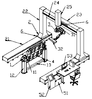
[0019] The non-contact three-dimensional automatic scanning test system includes a positioner 1, a gantry support 2, a robot 3, a measuring workpiece 4, and a data processing control system 5. The positioner 1 includes two support brackets 12 and a rotating clamping device 11. The support bracket 12 is provided with a motor and a gear inside, and the end of the support bracket 12 is provided with a rotating clamping device 11, and the measuring ...


PUM


Abstract

The invention discloses a non-contact three-dimensional automatic scanning testing system, and the system comprises a positioner, a portal frame, a robot, a measurement workpiece, and a data processing control system. The positioner comprises two supports and a rotating clamping device. The portal frame comprises two X-axis moving guide rails for a walking mechanism, two Y-axis moving support columns, and one Z-axis moving cross beam. The tops of the Y-axis moving support columns are provided with the Z-axis moving cross beam, and the Z-axis moving cross beam is provided with a moving guide rail and a robot installation support. The robot installation support is provided with a flange seat, and a robot is fixedly installed on the flange seat. An end part of the robot is provided with a 3Dscanning measurer. The 3D scanning measurer comprises a camera and a projector, and the data processing control system comprises a robot control cabinet, an electrical control cabinet, and a PLC operating system. The robot control cabinet is electrically connected with the robot. According to the technical scheme of the invention, the travel control range can be enlarged, and the measurement precision and detection efficiency are improved. The system timely collects, processes and displays the measurement data, and can meet the requirements of various angles, precisions and speeds of differentworkpieces, and can be widely used for online application.

Description

technical field [0001] The invention mainly relates to the field of three-dimensional measurement systems, in particular to a non-contact three-dimensional automatic scanning test system. Background technique [0002] The application of machine vision inspection equipment can improve and enhance the flexibility and automation of production and processing. It is widely used in industry, military, aerospace and other industries. It has become an automatic, high-precision, and high-efficiency measurement that replaces traditional manual measurement methods , with the rapid development of its visual technology and image technology, many products have emerged as the times require. Compared with traditional measurement methods, visual measurement equipment has the advantages of non-contact, high precision, fast and convenient. [0003] Now most of the visual measurement equipment of manufacturers is fixed by a tripod. This method is relatively slow in movement and measurement spee...

Claims


Application Information

Patent Timeline
IPC IPC(8): G01B11/25G05B19/05
CPCG01B11/2518G05B19/05G05B2219/15039
Inventor 汪建新汪志灵陈闯闯
Owner 苏州艾弗伦智能技术有限公司
Learn More