
Fin pitch measuring system and measuring method

A measurement system and measurement method technology, applied in the direction of measurement devices, instruments, optical devices, etc., can solve the problems of incompatibility, poor flexibility, and high cost of products with different sizes, and achieve reliable test methods, low cost, and satisfactory The effect of production process requirements

Pending Publication Date: 2018-11-23
YORK GUANGZHOU AIR CONDITIONING & REFRIGERATION +1
View PDF0 Cites 2 Cited by
  • Summary
  • Abstract
  • Description
  • Claims
  • Application Information

AI Technical Summary

Problems solved by technology

The disadvantage of this measurement method is that it is less flexible, because when measuring the fin spacing with a visual measurement system, it is necessary to set the corresponding reference point and measurement range for the imaging picture, which is suitable for a single standard product, but For a wide variety of products with different size differences, it cannot be used universally
Moreover, the cost of this measurement method is high. A visual measurement system generally consists of a camera, lens, light source, and bracket, and the cost ranges from tens of thousands to hundreds of thousands.

Method used


Image

  • Fin pitch measuring system and measuring method
  • Fin pitch measuring system and measuring method
  • Fin pitch measuring system and measuring method

Examples


Embodiment Construction

[0023] Various embodiments of the invention will be described below with reference to the accompanying drawings, which form a part hereof. It should be understood that although directional terms are used in the present invention, such as "front", "rear", "upper", "lower", "left", "right", "inner", "outer", etc. Various example structural parts and elements of the present invention, but these terms are used herein for convenience of description only, are based on the example orientations shown in the drawings. Since the disclosed embodiments of the present invention may be arranged in different orientations, these directional terms are for illustration only and should not be viewed as limiting. Where possible, the same or similar reference numerals used in the present invention refer to the same components.

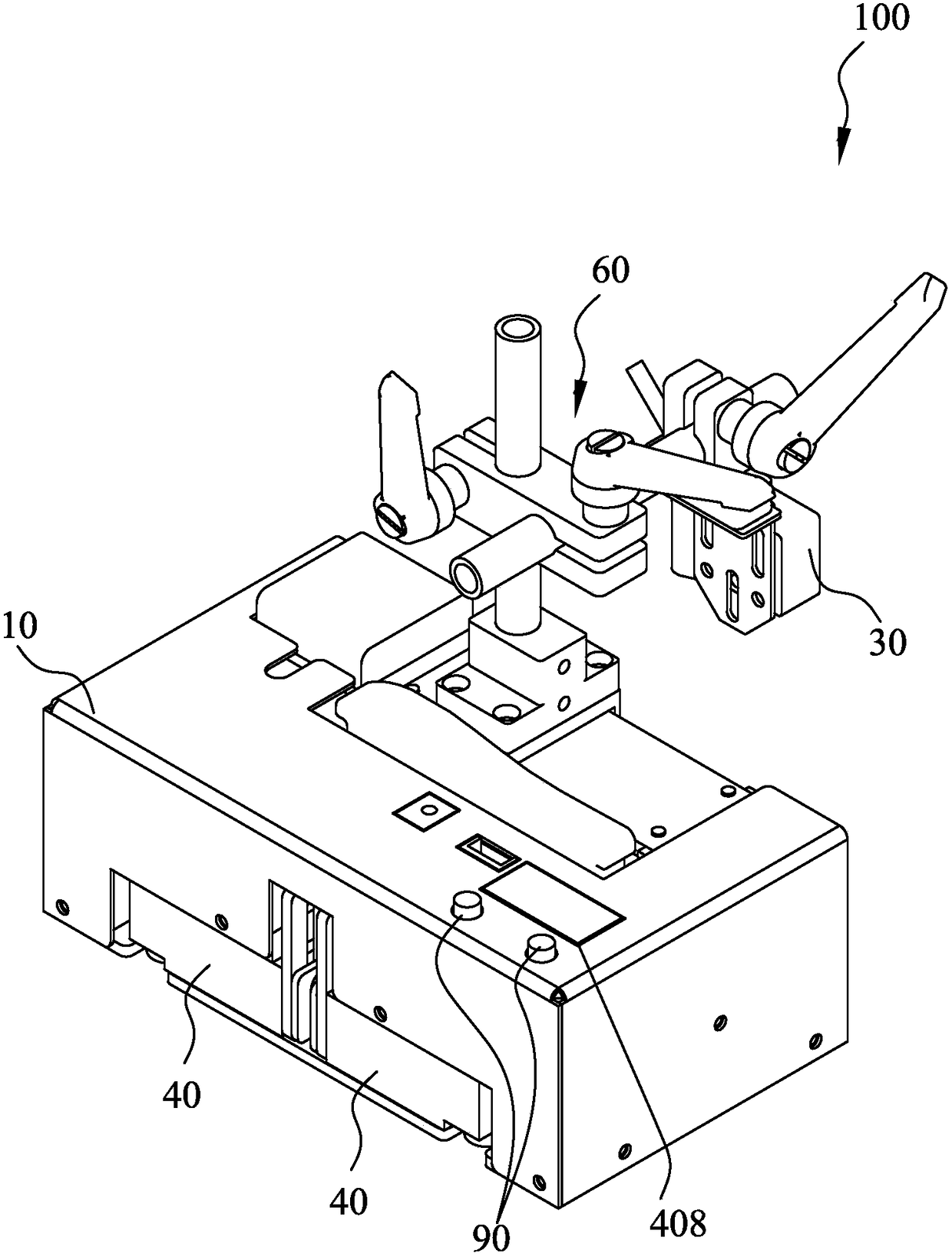
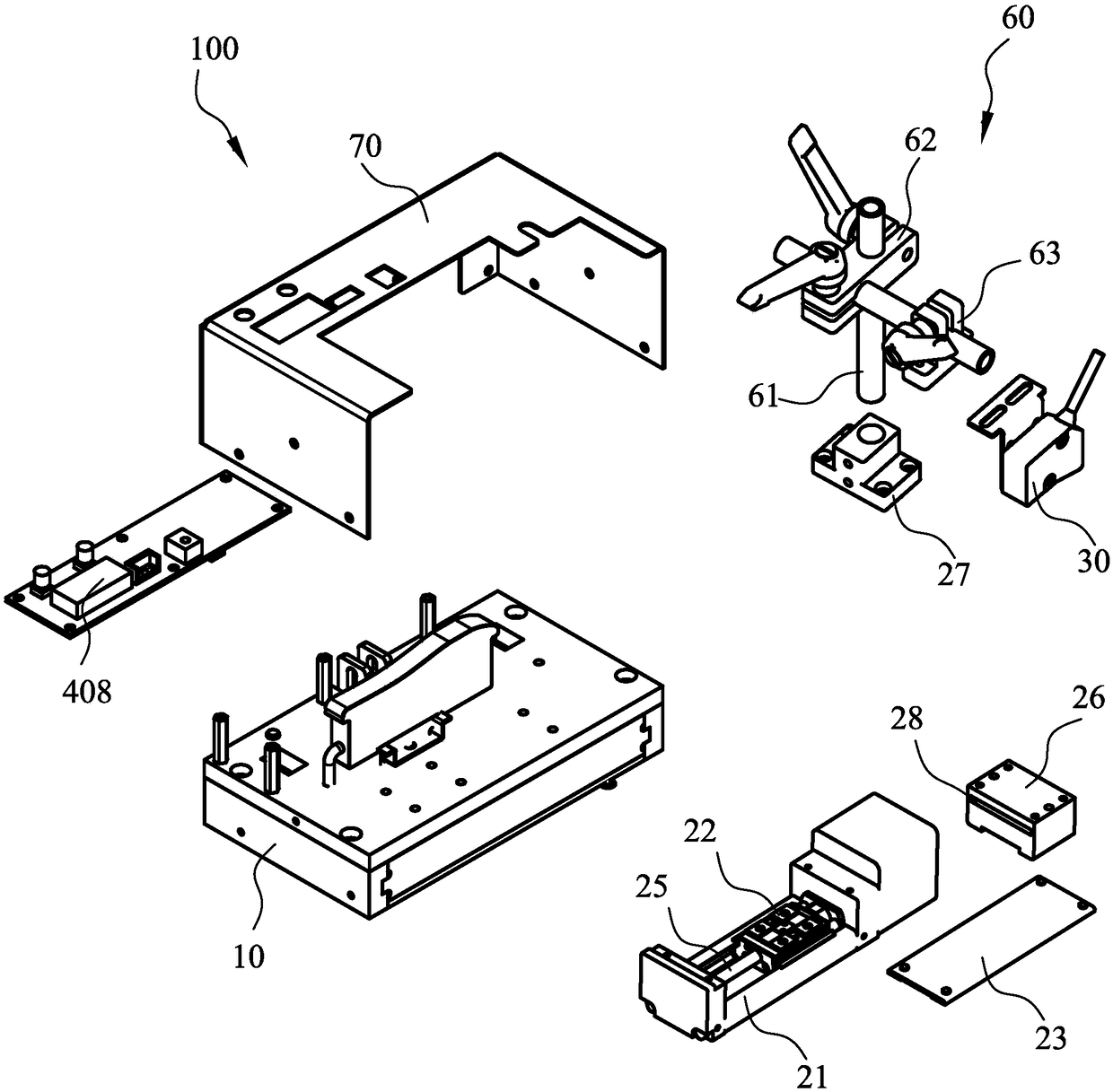
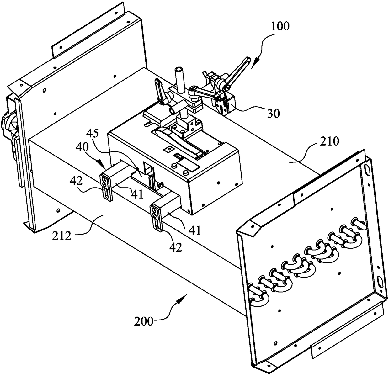
[0024] Figure 1A A perspective view of a fin-to-fin distance measuring system 100 according to the present invention is shown, while Figure 1B is an exploded view of t...


PUM


Abstract

The present invention provides a fin pitch measuring system. The system comprises a base, a moving device, a driving device and a laser generating and receiving device, wherein the moving device is arranged on the base, the driving device is used for driving, the laser generating and receiving device is disposed on the moving device, the laser generating and receiving device is configured to emitlaser toward fins and is capable of receiving laser reflected from the fins; the system further comprises a signal conversion circuit, a moving distance indication device, and a processor, wherein thesignal conversion circuit is connected with the laser generating and receiving device, and is configured to generate fin indication signals according to received laser is reflected when the laser scans the fins, the moving distance indication device is connected with the output end of the driving device and is configured to move along with the moving device so as to generate moving distance indication signals, and the processor is connected with the signal conversion circuit and the moving distance indication device and is configured to determine whether the pitch of the measured pins is qualified according to the fin indication signals and the moving distance indication signals. The fin pitch measuring system of the invention has the advantages of simple structure, low cost and reliabletesting method.

Description

technical field [0001] The present invention relates generally to testing of finned heat exchanger fabrication, and more particularly to systems and methods for measuring fin pitch. Background technique [0002] The heat exchange device increases the heat exchange surface area through a series of fins arranged in parallel and spaced apart from each other installed on its base tube. Whether the fin spacing is qualified directly affects the working efficiency of the heat exchange device. In the process of manufacturing the heat exchange device, the fins are formed by the process of punching and expanding the tubes. After punching and expanding the fins, the distance between the fins needs to be measured, and according to the measurement results of the fin distances, the Correct the mold adjustment of the punching machine to produce qualified products within the allowable range of the finned heat exchanger process standard. [0003] At present, there are mainly two methods fo...

Claims


Application Information

Patent Timeline
Patent Type & Authority Applications(China)
IPC IPC(8): G01B11/14
CPCG01B11/14
Inventor 李红松韦留坤
Owner YORK GUANGZHOU AIR CONDITIONING & REFRIGERATION
Learn More