A waste heat recovery pipeline for a hot blast stove

A technology of waste heat recovery and hot blast stove, which is applied in the direction of fluid heaters, lighting and heating equipment, etc., can solve the problems of waste heat recovery pipes loosening, recovery pipes scalding, staff scalding, etc., and achieve the effect of solving waste heat recovery pipes loosening

Active Publication Date: 2020-11-27
安徽永鹏机械有限公司
View PDF14 Cites 0 Cited by
  • Summary
  • Abstract
  • Description
  • Claims
  • Application Information

AI Technical Summary

Problems solved by technology

[0003] The purpose of the present invention is to provide a waste heat recovery pipeline for hot blast stoves, to solve the problem that the existing waste heat recovery pipelines for hot blast stoves mentioned in the background art are used because the internal machine works, causing the recovery pipeline to vibrate during work, and it will continue to work for a long time. The waste heat recovery pipe is loose, and when it is used for a long time, the waste heat will be transferred to the outer surface of the hot blast stove. The recovery pipe will cause it to be very hot, which will easily cause the staff to be scalded.

Method used


Image

  • A waste heat recovery pipeline for a hot blast stove
  • A waste heat recovery pipeline for a hot blast stove
  • A waste heat recovery pipeline for a hot blast stove

Examples


Embodiment 1

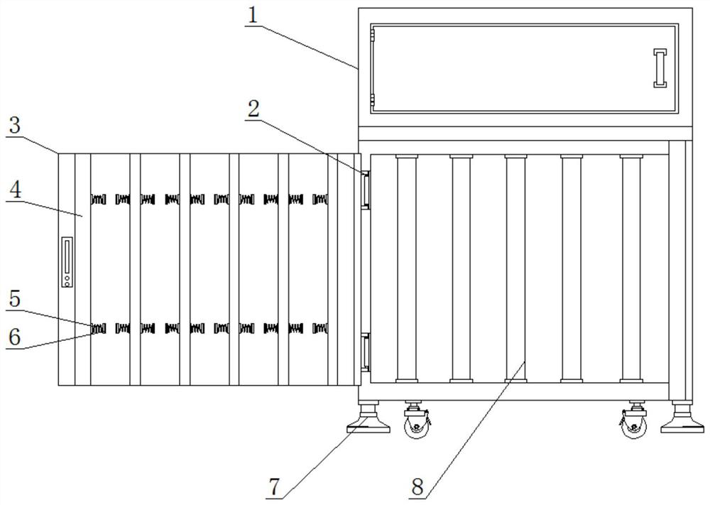
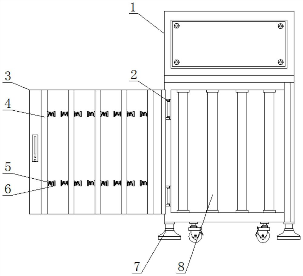
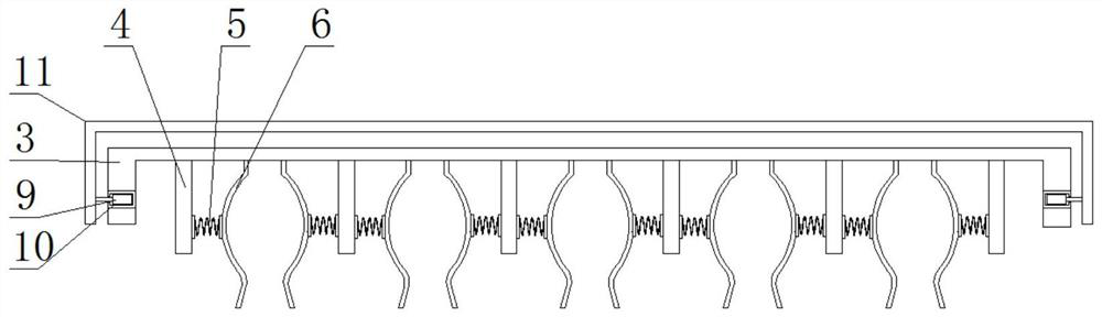
[0018] see figure 1 , figure 2 and image 3 , the present invention provides a technical solution: a waste heat recovery pipeline for a hot blast stove, comprising a hot blast stove main body 1, the outer surface of the hot blast stove main body 1 is equipped with a hot blast stove inner fixed cover 3, and the hot blast stove inner fixed cover 3 is connected with the hot blast A hinge 2 is fixedly installed at the joint of the furnace main body 1, a fixed block 4 is arranged on the upper surface of the fixed cover 3 in the hot blast stove, a spring 5 is installed on one side of the fixed block 4, and a clamp 6 is fixedly installed on one end of the spring 5. The upper surface of the inner fixed cover 3 is equipped with a hot blast stove outer protective cover 11, and the inner two ends of the hot blast stove outer protective cover 11 are provided with clamping blocks 9, and the connection between the clamping blocks 9 and the hot blast stove inner fixed cover 3 is provided w...

Embodiment 2

[0024] see figure 1 , figure 2 and image 3 , the present invention provides a technical solution: a waste heat recovery pipeline for a hot blast stove, comprising a hot blast stove main body 1, the outer surface of the hot blast stove main body 1 is provided with a hot blast stove inner fixed cover 3, and the hot blast stove inner fixed cover 3 is connected with the hot blast A hinge 2 is provided at the joint of the furnace main body 1, a fixed block 4 is provided on the inner surface of the fixed cover 3 in the hot blast stove, a spring 5 is arranged on one side of the fixed block 4, and a clamp 6 is arranged on one end of the spring 5, and the fixed block 4 is arranged in the hot blast stove. The upper surface of the cover 3 is provided with an outer protective cover 11 of the hot blast stove, and both ends of the outer protective cover 11 of the hot blast stove are provided with a block 9, and the connection between the block 9 and the inner fixed cover 3 of the hot bla...


PUM


Abstract

The invention discloses a waste heat recycling pipeline for a hot-blast stove. The waste heat recycling pipeline for the hot-blast stove comprises a hot-blast stove main body, the periphery of the outer surface of the hot-blast stove main body is provided with hot-blast stove inner fixing covers, and the joints of the hot-blast stove inner fixing covers and the hot-blast stove main body are provided with hinges. The internal surfaces of the hot-blast stove inner fixing covers are provided with fixing blocks, one sides of the fixing blocks are provided with springs, one ends of the springs areprovided with fixtures, and the upper surfaces of the hot-blast stove inner fixing covers are provided with hot-blast stove outer protection covers. The hot-blast stove outer protection covers are designed on the outer surfaces of the hot-blast stove inner fixing covers, the problem that when the hot-blast stove is used for a long time, waste heat is transferred to the external surface of the hot-blast stove, the external surface of the hot-blast stove is hot due to the recycling pipeline, and workers are prone to be scalded is solved, the inner fixing covers and the outer protection covers ofthe hot-blast stove can be clamped and fixed by clamping clamping-blocks into clamping slots, and the problem that the external surface of the hot-blast stove is hot due to the recycling pipe, and thus the workers are prone to be scalded is solved.

Description

technical field [0001] The invention belongs to the technical field of waste heat recovery pipelines, and in particular relates to a waste heat recovery pipeline for hot blast stoves. Background technique [0002] Existing waste heat recovery pipes for hot blast stoves are devices connected by pipes, pipe connectors and valves to transport gas, liquid or fluid with solid particles. For example, when used in hot blast stoves, the hot blast stove can be The waste heat inside is recycled; the existing waste heat recovery pipes for hot blast stoves vibrate during operation due to the operation of the internal machine, and the waste heat recovery pipes will loosen after a long time of work. When used for a long time, the waste heat will be transferred The external surface of the hot blast stove is very hot due to the recovery pipe, which easily causes the staff to be scalded. Therefore, we propose a waste heat recovery pipe for the hot blast stove. Contents of the invention ...

Claims


Application Information

Patent Timeline
Patent Type & Authority Patents(China)
IPC IPC(8): F24H9/00
CPCF24H9/2064
Inventor 薛振义
Owner 安徽永鹏机械有限公司
Why Eureka
Try Eureka