Eureka AIR delivers breakthrough ideas for toughest innovation challenges, trusted by R&D personnel around the world.

Mobile air conditioner

An air conditioner and water tank technology, applied in the field of air conditioning, can solve problems such as user inconvenience, damage to mobile air conditioners, and low efficiency of condensed water use, and achieve the effects of increasing structural rationality, improving cooling efficiency, and increasing use time

Pending Publication Date: 2018-11-23
AUX AIR CONDITIONING LTD BY SHARE LTD
View PDF0 Cites 9 Cited by
  • Summary
  • Abstract
  • Description
  • Claims
  • Application Information

AI Technical Summary

Problems solved by technology

However, in the prior art, the three-layer water trays fail to form a good cooperation, which is not conducive to the overall water scheduling of the mobile air conditioner, and the use efficiency of condensed water is low
And when the air is blown from the top of the mobile air conditioner, condensed water will condense on the top plate, and the condensed water will accumulate too much and flow down the side wall or panel of the mobile air conditioner, causing inconvenience to the user; the middle water tray cannot discharge excess water in time, resulting in condensation Water overflows or flows into other electrical components, damaging the mobile air conditioner; the chassis can be divided into four areas according to its water channels, namely: water level control area, water absorption area, sink area and water collection area, among which the water tank area and water absorption area, water collection area Connected, the water tank area is used to buffer the water on the chassis, the water in the water pumping area can be pumped to the condenser fins to evaporate through the water pumping wheel, and the water in the water suction area is pumped out
Whether the structural design of the chassis of the mobile air conditioner is reasonable will directly affect the efficiency, service life, and length of use of the mobile air conditioner, etc.

Method used


Image

  • Mobile air conditioner
  • Mobile air conditioner
  • Mobile air conditioner

Examples


Embodiment 1

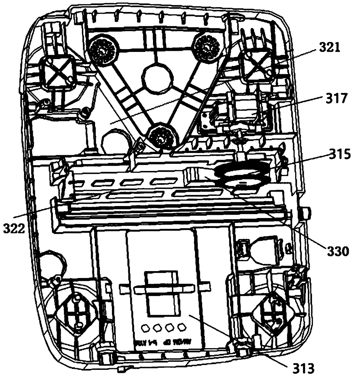
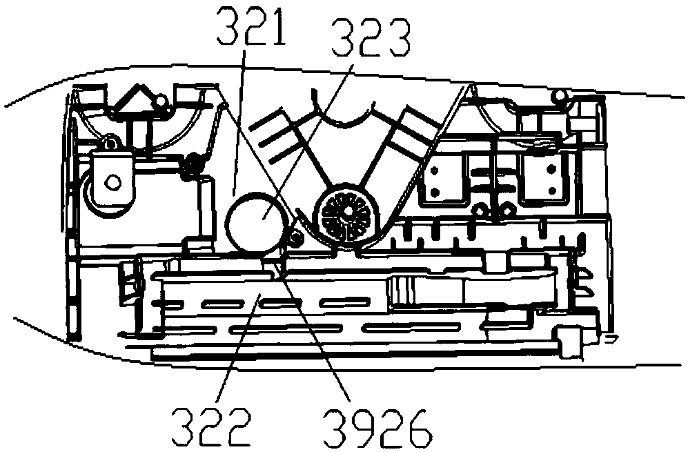
[0092] The invention provides a mobile air conditioner. The mobile air conditioner includes a chassis structure combined with Figure 1 to Figure 5 As shown, the chassis structure includes: water absorption area 321, water level control area 313, tank area 322 and water drawing area 330; The chassis structure also includes:

[0093] A connection channel 3625 is arranged between the water absorption area 321 and the water tank area 322, and is used for the connection between the water absorption area 321 and the water tank area 322;

[0094] At least one water retaining rib 3926 is arranged at any position in the axial direction of the connecting channel 3925 parallel to the cross section of the connecting channel, and is used to isolate the water absorption area 321 from the water tank area 322.

[0095] Water retaining ribs 3926 are used to isolate the water absorption area 321 from the water tank area 322, so that the water tank area 322 can store a certain amount of water. ...

Embodiment 2

[0099] As the mobile air conditioner described above, the difference of this embodiment is that, in combination with Figure 6 , Figure 7 As shown, the chassis structure also includes: a converging portion 332, which is used to connect the water tank area 322 and the water-drawing area 330, which is located between the water-drawing area 330 and the water tank area 322, and is close to the converging port 331 of the water-drawing area 330;

[0100] The converging part 332 is a concave structure with a low middle and high surroundings. The advantage of this arrangement is that before the accumulated water enters the water-drawing area 330, the accumulated water is preferentially introduced into the converging part 332, so that a part of the accumulated water is buffered in the converging part 332; at the same time, Alleviate the speed at which accumulated water enters the water pumping area 330, and reduce the load of the water pumping wheel.

[0101] Preferably, the concave ...

Embodiment 3

[0109] Like the mobile air conditioner described above, the difference of this embodiment is that the mobile air conditioner also includes a water pumping structure, which is used to scatter the condensed water to the fins of the condenser, combined with Figure 8 to Figure 10 As shown, the water pumping structure includes: a water tank 316, which is used to accumulate condensed water; at least one water wheel 315, which is at least partially accommodated in the water tank 316, and the accumulated condensed water in the water tank 316 is removed. Sprinkling; a water pumping motor 317, which is connected with the water pumping wheel 315, and drives the water pumping wheel 315 to rotate; the bottom surface of the water pumping tank 316 is a tank body 318, and the tank body 318 is along the radial direction of the water pumping wheel 315 from both ends to the middle Concave, and then form a groove structure with high sides and low middle; the structure of the tank body 318 can mak...


PUM

PropertyMeasurementUnit
Heightaaaaaaaaaa
Heightaaaaaaaaaa
Heightaaaaaaaaaa

Abstract

The invention provides a mobile air conditioner. The mobile air conditioner comprises an upper water receiving disc, a middle water receiving disc and a chassis structure, the chassis structure comprises a water absorption area, a water tank area, a water splashing area and a water level control area, and further comprises water retaining ribs used for isolating the water absorption area from thewater tank area and a convergence part which is positioned between the water splashing area and the water tank area and is close to a convergence port of the water splashing area, wherein the water splashing wheel is arranged in the convergence part. According to the mobile air conditioner, the cooperation among the upper water receiving disc, the middle water receiving disc and a chassis is adopted, therefore, water correspondingly in the upper water receiving disc, the middle water receiving disc and the chassis in the air conditioner can be reasonably distributed, the water is preferentially supplied to the water splashing area, moreover, the water in the upper layer and the water in the middle layer can be directly supplied to the water splashing area, the water circulation step is reduced, and the water splashing efficiency is improved.

Description

technical field [0001] The invention relates to the technical field of air conditioning, in particular to a mobile air conditioner. Background technique [0002] Compared with the traditional vertical air conditioner, the mobile air conditioner is smaller in size, does not need to be installed, and is easy to move. It can be placed in different positions in the house at will. Existing mobile air conditioner is usually divided into three layers of water receiving trays according to its structure, i.e. upper floor water receiving tray, middle floor water receiving tray, chassis. However, in the prior art, the three-layer water receiving trays fail to form a good cooperation, which is not conducive to the overall water scheduling of the mobile air conditioner, and the use efficiency of condensed water is low. And when the air is blown from the top of the mobile air conditioner, condensed water will condense on the top plate, and the condensed water will accumulate too much and...

Claims


Application Information

Patent Timeline
IPC IPC(8): F24F1/02F24F13/22
CPCF24F1/022F24F13/222
Inventor 冷晓刚成日雄陈明侠王长刚耿德国
Owner AUX AIR CONDITIONING LTD BY SHARE LTD
Why Eureka
Eureka Blog
Learn More