
Intelligent single-spindle charge coupled device (CCD) engraving and milling machine

A fine engraving machine and single-axis technology, which is applied to metal processing machinery parts, televisions, maintenance and safety accessories, etc. It can solve the problems of CCD cameras being destructive, the rigidity of the gantry frame is reduced, and the processing range is narrowed, so as to save loading and unloading The effect of saving time, protecting the CCD camera, and improving processing efficiency

Pending Publication Date: 2018-11-23
SHENZHEN JOJOY BEN MACHINERY EQUIP
View PDF0 Cites 1 Cited by
  • Summary
  • Abstract
  • Description
  • Claims
  • Application Information

AI Technical Summary

Problems solved by technology

[0004] In the Jingdiao machine, the harsh environment such as cutting fluid and water mist is very destructive to the CCD camera for visual measurement. It will not only interfere with the normal shooting of the camera, but also reduce its mission. For example, the cutting fluid will enter the lens of the CCD camera , the lens will be scrapped, causing great trouble to the producer
In addition, the CCD cameras in Jingdiao machines are all set on the left or right side of the engraving device. Such a positional relationship will limit the moving position of the CCD camera. For example: the CCD camera is installed on the right side of the Z axis. If X The stroke is 830mm as the width of the workbench, because the processing axis and the CCD camera need to reach a certain position when processing the product, so the processing range is reduced to 565mm
If the processing range is 830mm, the X stroke needs to be increased to 1095mm, so that the length of the gantry needs to be relatively increased, so that the rigidity of the gantry will be greatly reduced, and the processing difficulty and cost of the gantry will also be greatly increased.

Method used


Image

  • Intelligent single-spindle charge coupled device (CCD) engraving and milling machine
  • Intelligent single-spindle charge coupled device (CCD) engraving and milling machine
  • Intelligent single-spindle charge coupled device (CCD) engraving and milling machine

Examples


Embodiment Construction

[0035] The present invention will be further described below in conjunction with specific embodiments and accompanying drawings.

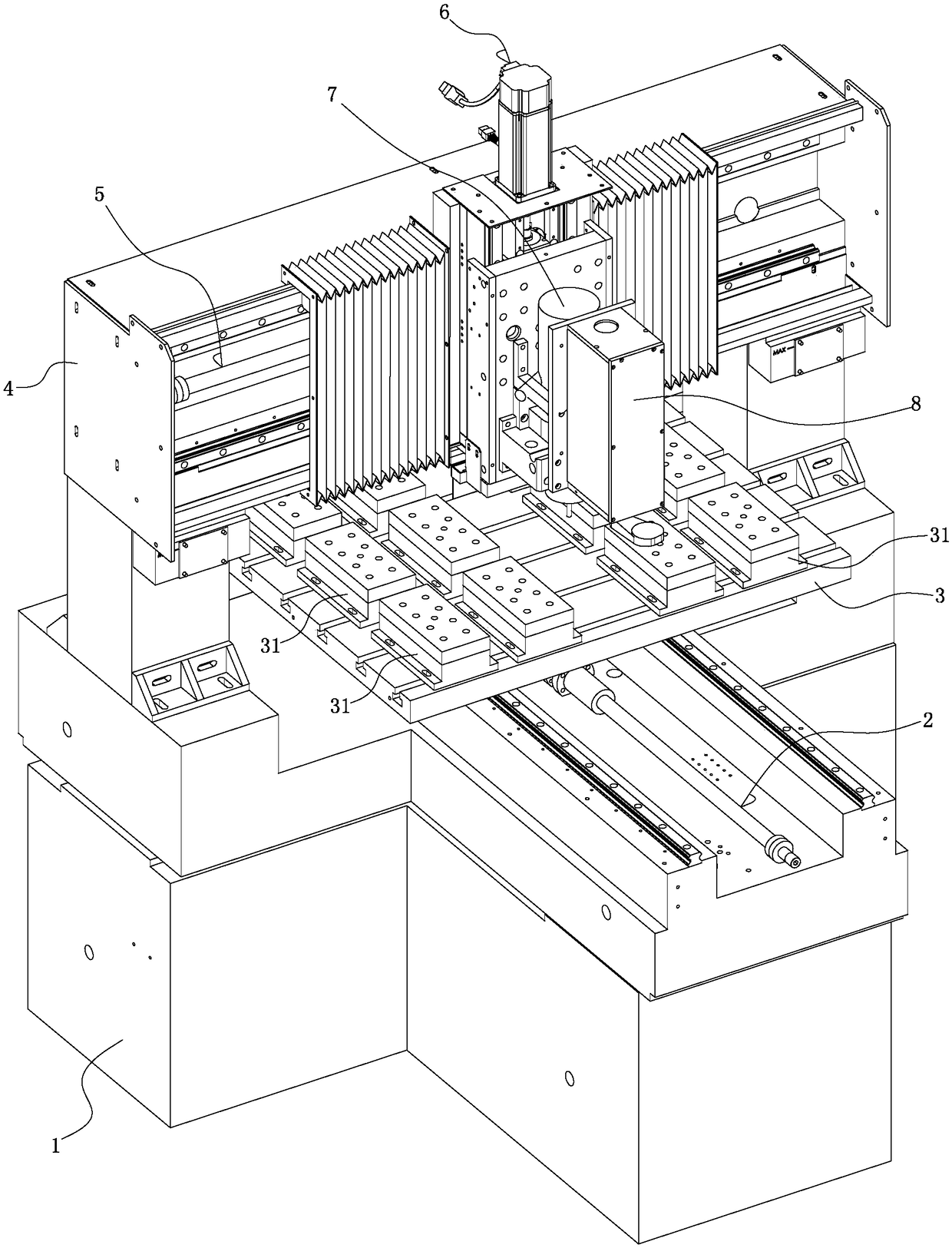
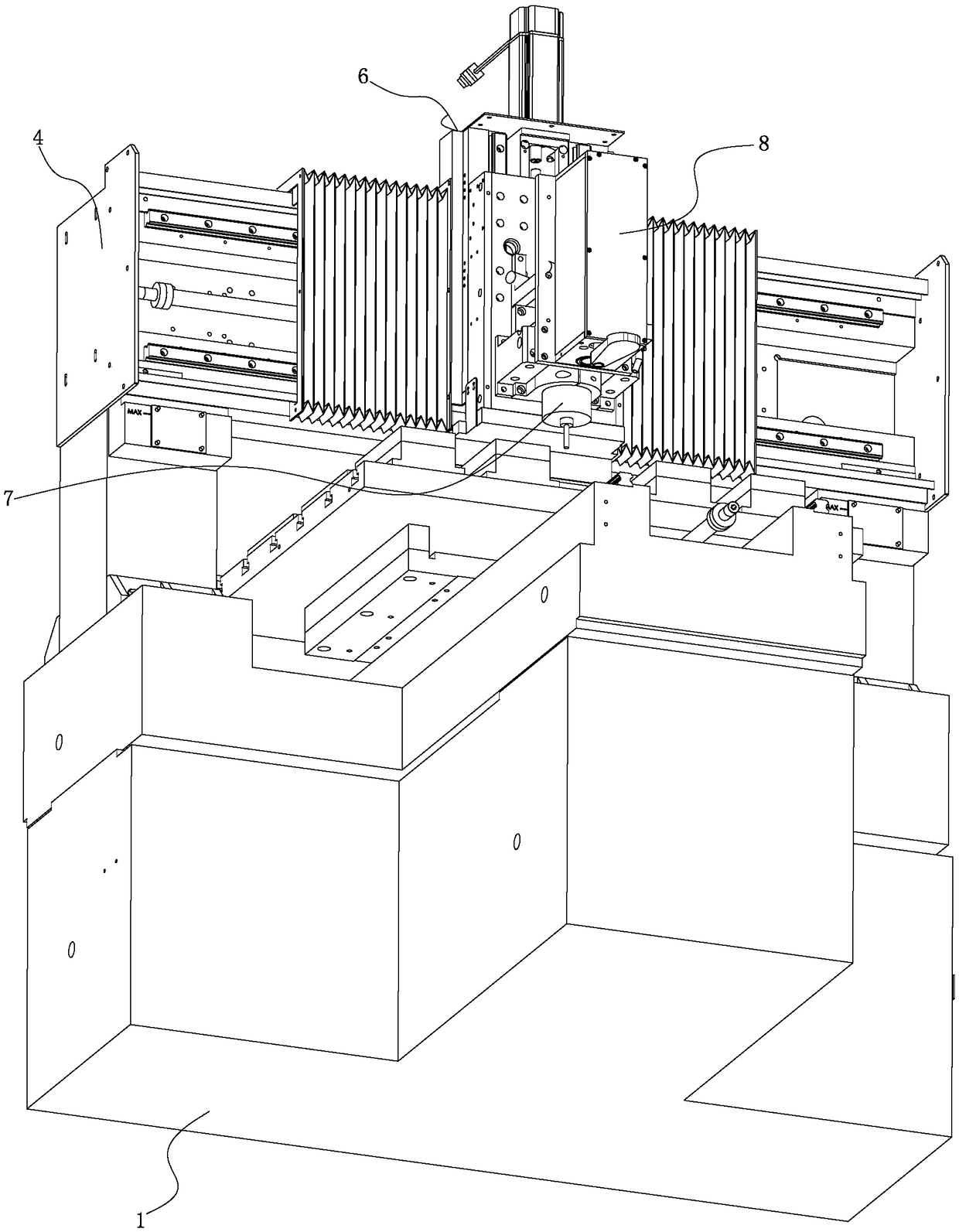
[0036] See Figure 1-11 As shown, it is an intelligent single-axis CCD engraving machine, which includes: a machine base 1, a Y-axis linear drive device 2 installed on the machine base 1, and a Y-axis linear drive device 2 installed on the Y-axis linear drive device. The driving device 2 drives the workbench 3 to move in the Y-axis direction, the gantry 4 installed on the machine base 1, the X-axis linear drive 5 installed on the gantry 4 and the X-axis linear drive 5 and A Z-axis linear drive device 6 driven by the X-axis linear drive device 5 to move in the X-axis direction, and an engraving device mounted on the Z-axis linear drive device 6 and driven by the Z-axis linear drive device 6 to move in the Z-axis direction 7. The X-axis linear drive device 5 and the engraving device 7 are located above the workbench 3, and the workbench 3 is provide...


PUM


Abstract

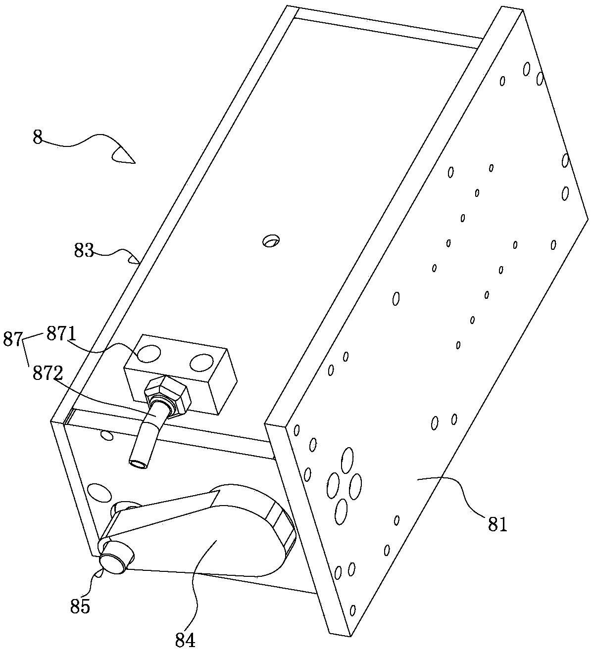
The invention discloses an intelligent single-spindle charge coupled device (CCD) engraving and milling machine which comprises a machine base, a Y-axis linear driving device arranged on the machine base, a working table arranged on the Y-axis linear driving device, a portal frame arranged on the machine base, an X-axis linear driving device arranged on the portal frame, a Z-axis linear driving device arranged on the X-axis linear driving device, and an engraving device arranged on the Z-axis linear driving device. A jig is arranged on the working table; a CCD camera assembly is arranged on the Z-axis linear driving device, is located at the front end of the engraving device, and comprises a base plate fixed onto the Z-axis linear driving device, and a CCD camera arranged on the base plate; a protection cover is arranged on the periphery of the base plate and covers the periphery of the CCD camera; a lens hole corresponding to the CCD camera is formed in the lower end of the protectioncover; a lens of the CCD camera faces the lens hole; the protection cover is provided with a lens cover matched with the lens hole, and a drive mechanism for controlling the lens cover to open or close the lens hole.

Description

Technical field: [0001] The invention relates to the technical field of fine carving, in particular to an intelligent single-axis CCD fine carving machine. Background technique: [0002] The engraving machine in the prior art generally includes an organic base, a Y-axis linear drive device installed on the base, and a working device that is installed on the Y-axis linear drive device and driven by the Y-axis linear drive device to move in the Y-axis direction. platform, a gantry mounted on the machine base, an X-axis linear drive device mounted on the gantry, and a Z-axis linear drive mounted on the X-axis linear drive device and driven by the X-axis linear drive device to move in the X-axis direction The driving device and the engraving device installed on the Z-axis linear driving device and driven by the Z-axis linear driving device to move in the Z-axis direction, the X-axis linear driving device and the engraving device are located above the workbench, and the workbench...

Claims


Application Information

Patent Timeline
IPC IPC(8): B23Q17/00B23Q17/24B23Q11/08H04N5/225
CPCB23Q11/08B23Q17/00B23Q17/24B23Q17/249H04N23/51H04N23/00
Inventor 廖艺龙韦禄左选兰
Owner SHENZHEN JOJOY BEN MACHINERY EQUIP
Learn More