Bogie bearing spring disassembling process
A dismantling process and bogie technology, applied in metal processing, manufacturing tools, metal processing equipment, etc., can solve the problems of potential safety hazards, high labor intensity, low work efficiency, etc., to improve disassembly efficiency, reduce labor intensity, improve The effect of pick and place efficiency
- Summary
- Abstract
- Description
- Claims
- Application Information
AI Technical Summary
Problems solved by technology
Method used
Image


Examples
Embodiment 1
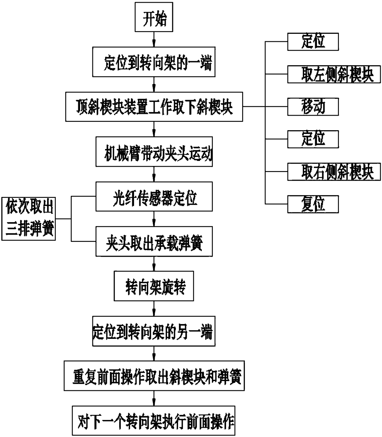
[0052] The bogie bearing spring dismounting process of the present invention comprises the following steps:
[0053] S1 is positioned to one end of the bogie 5;
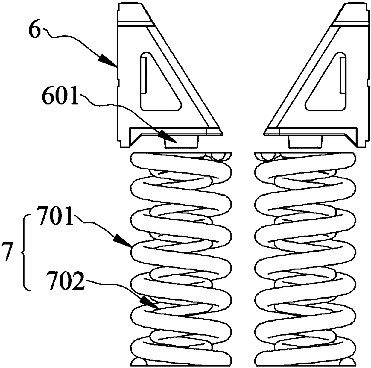
[0054] The S2 jacking device works to remove the wedge block 6;
[0055] The jacking device includes a jacking unit 4 and a three-axis cantilever. There are two jacking units 4, and the movement of the jacking unit 4 in space is realized through the three-axis cantilever, and the wedge on the left side of one of the jacking units 4 is completed. Positioning of the block 6, then remove the left wedge block 6, then move another jacking unit 4 to position the right wedge block 6, then go to the right wedge block 6, and finally reset;
[0056] S3 mechanical arm 2 drives chuck 1 to move;
[0057] The chuck 1 and the mechanical arm 2 are connected to each other through a flange 10;
[0058] S4 positioning device locates the bearing spring 7;
[0059] The through-beam optical fiber sensor 1021 positions the outer spring...
Embodiment 2
[0066] as attached Figure 3-4 As mentioned, the present embodiment is optimized as follows on the basis of Embodiment 1: the three-axis cantilever in the S2 step includes an X-axis guide rail (801), a Y-axis guide rail (802) and a Z-axis guide rail (802) all equipped with ball screws. Guide rail (803), the lower end of the three-axis cantilever is provided with a bracket (3), the X-axis guide rail (801) is horizontally arranged on the upper end of the bracket (3), and the Y-axis guide rail (802) is horizontally arranged on the X-axis guide rail ( The upper end of 801) is perpendicular to the X-axis guide rail, and the lower end of the middle part of the Y-axis guide rail (802) is connected with a first sliding seat (8011), and the first sliding seat (8011) and the X-axis guide rail (801) are connected to each other, The upper end of the Y-axis guide rail (802) is vertically connected with a Z-axis guide rail (803), and the lower end of the Z-axis guide rail (803) is connected...
Embodiment 3
[0069] as attached Figure 5-6 As shown, this embodiment is based on Embodiment 2, and the following optimizations are made: the Z-axis guide rail (803) is also connected with a third sliding seat (8031), and the jacking unit (4) is provided with two and are symmetrical about the Z-axis guide rail (803), and the two jacking units (4) are connected to the third sliding seat (8031); the jacking unit (4) includes a laser sensor, a connecting plate (401), a jacking Lifting platform (403), jacking rod (406) and small cylinder (407), described connecting plate (401) interconnects jacking platform (403) and the 3rd sliding seat (8031), and described jacking platform ( 403) The upper end is provided with a laser sensor, the middle part of the lower end of the jacking platform (403) is provided with a lifting plate (405), the lifting plate (405) is provided with a U-shaped card slot, and the lifting plate (405) Jacking rods (406) are provided on the left and right sides of the jacking...
PUM
 Abstract
Description
Claims
Application Information
 - R&D
- Intellectual Property
- Life Sciences
- Materials
- Tech Scout
- Unparalleled Data Quality
- Higher Quality Content
- 60% Fewer Hallucinations
Browse by: Latest US Patents, China's latest patents, Technical Efficacy Thesaurus, Application Domain, Technology Topic, Popular Technical Reports.
© 2025 PatSnap. All rights reserved.Legal|Privacy policy|Modern Slavery Act Transparency Statement|Sitemap|About US| Contact US: help@patsnap.com