
Clamping robot structure

A clamping mechanism and robot technology, applied in the direction of chucks, manipulators, program-controlled manipulators, etc., can solve the problems of slow response speed, single control mode, and difficult wiring of air pipes, etc., and achieve fast response speed and high pick-and-place efficiency Effect

Pending Publication Date: 2019-04-12
DONGGUAN CHAOYE PRECISION EQUIPMENT CO LTD
View PDF0 Cites 4 Cited by
  • Summary
  • Abstract
  • Description
  • Claims
  • Application Information

AI Technical Summary

Problems solved by technology

[0003] The existing mature technologies all use a combination of multiple cylinders and slide rails to realize the lifting, opening and closing actions of the manipulator, because the driving medium of the cylinders is compressed air, which has slow response speed, single control mode, and difficulty in air pipe wiring, etc. Problem; moreover, because it is air-controlled, multiple actions cannot be linked and coordinated, resulting in low efficiency of the entire manipulator.

Method used


Image

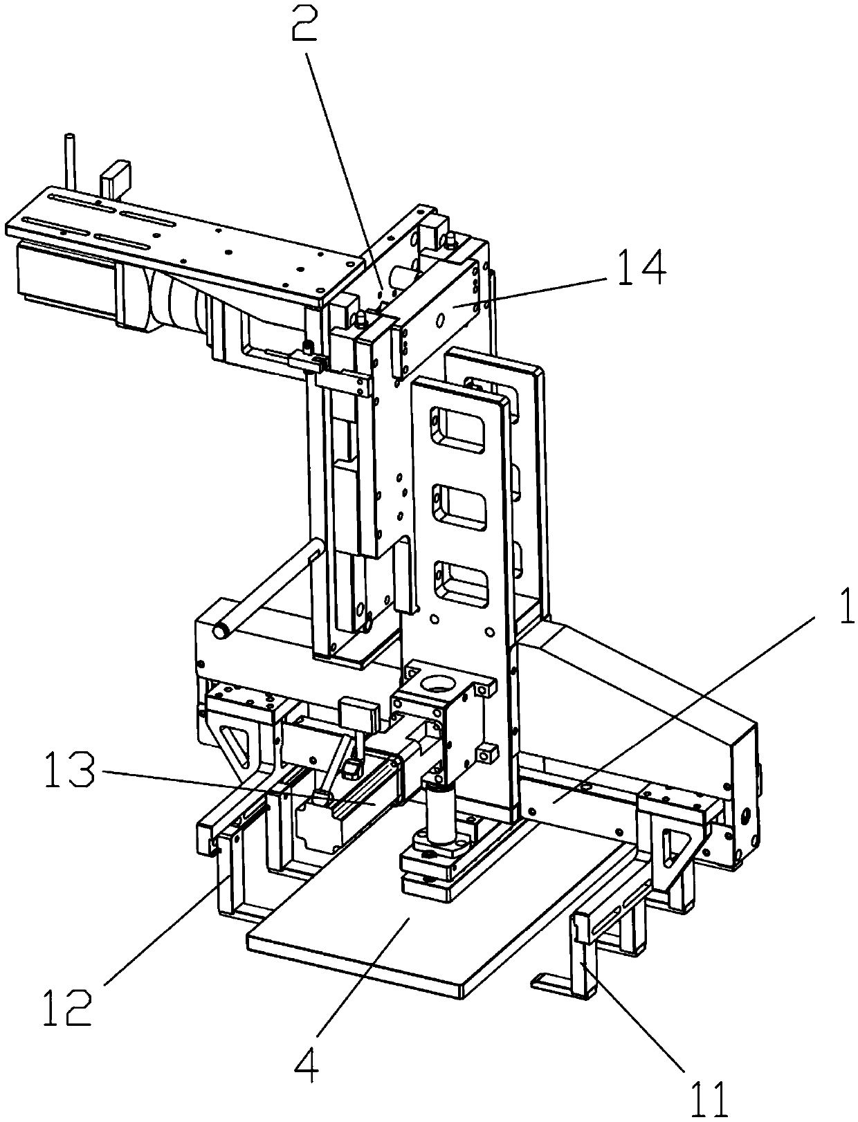
  • Clamping robot structure
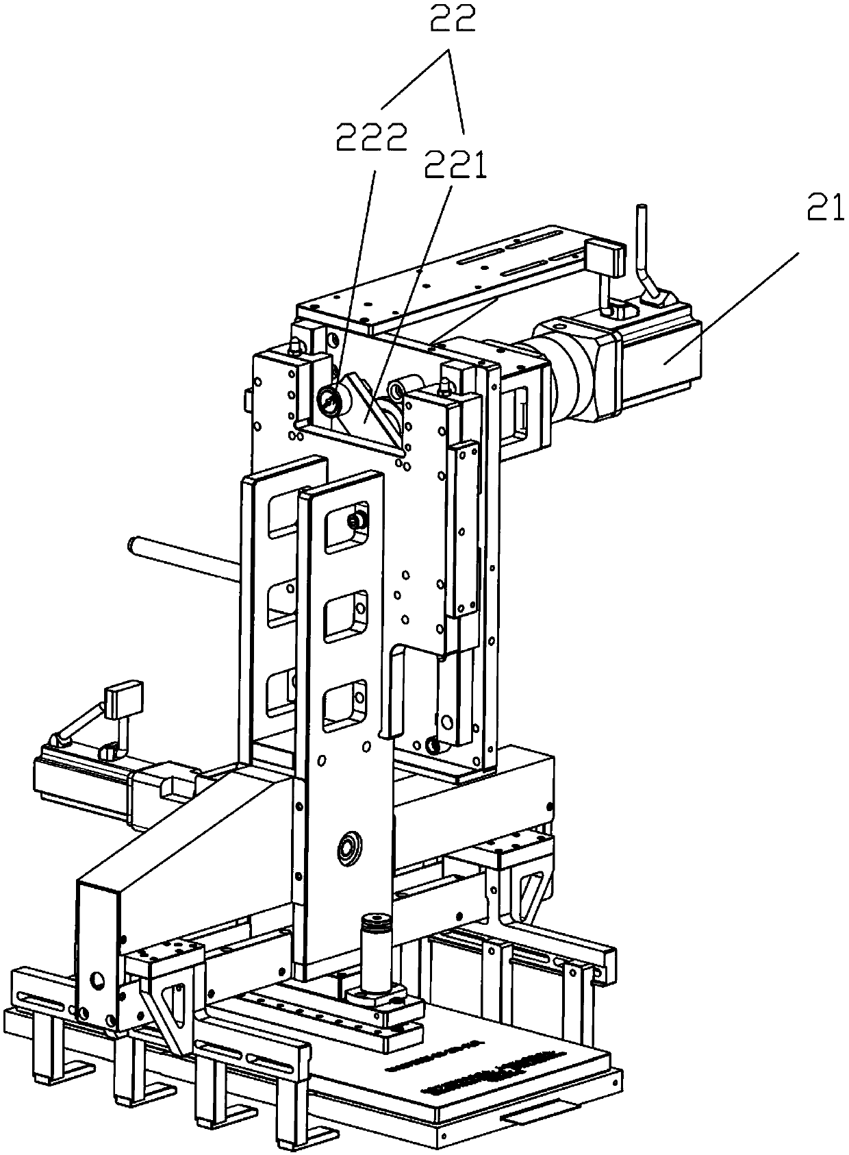
  • Clamping robot structure
  • Clamping robot structure

Examples


Embodiment Construction

[0029] Embodiments of the present invention are described below through specific examples, and those skilled in the art can easily understand other advantages and effects of the present invention from the content disclosed in this specification. The present invention can also be implemented or applied through other different specific implementation modes, and various modifications or changes can be made to the details in this specification based on different viewpoints and applications without departing from the spirit of the present invention.

[0030] It should be noted that the structures shown in the drawings of this specification are only used to cooperate with the content disclosed in the specification for the understanding and reading of those who are familiar with this technology, and are not used to limit the conditions for the implementation of the present invention. Therefore, It has no technical substantive meaning, and any modification or adjustment of the structur...


PUM


Abstract

The invention relates to the technical field of battery production equipment, in particular to a clamping robot structure. The clamping robot structure comprises a clamping mechanism and a lifting driving mechanism for driving the clamping mechanism to move in the vertical direction. The clamping mechanism comprises a first clamping assembly, a second clamping assembly and a connecting rod drive assembly, wherein the connecting rod drive assembly is used for driving the first clamping assembly and the second clamping assembly to get close to each other or get away from each other. The clampingrobot structure has the characteristic of being high in response speed, the ascending, descending and clamping actions can be conducted at the same time, and the robot taking and placing efficiency is improved.

Description

technical field [0001] The invention relates to the technical field of battery production equipment, in particular to a clamping robot structure. Background technique [0002] The pouch power battery welding machine (hereinafter collectively referred to as the welding machine) is located in the middle and front of the pouch battery production line, and is an indispensable model in the production of pouch batteries. The welding machine integrates many crucial processes in the front end of the total process of making pouch batteries, including the two necessary processes: cell loading and positioning, and cell ultrasonic welding. Handling and transfer between processes. [0003] The existing mature technologies all use a combination of multiple cylinders and slide rails to realize the lifting, opening and closing actions of the manipulator, because the driving medium of the cylinders is compressed air, which has slow response speed, single control mode, and difficulty in air ...

Claims


Application Information

Patent Timeline
Patent Type & Authority Applications(China)
IPC IPC(8): B25J9/00B25J15/00
CPCB25J9/00B25J15/00
Inventor 梁桂庆张世平刘浩
Owner DONGGUAN CHAOYE PRECISION EQUIPMENT CO LTD
Learn More