Reeling-type automatic cleaning floor mopping machine

An automatic cleaning and mopping machine technology, which is applied to manual floor scrubbing machines, carpet cleaning, floor cleaning, etc. It can solve the problems of poor stirring effect, long cleaning pool, and excessive water consumption, and achieve good dehydration effect and wide range. Wide working width and easy cleaning

Active Publication Date: 2018-11-23
SUINING CHANGFENG MECHANICAL TECH
View PDF9 Cites 5 Cited by
  • Summary
  • Abstract
  • Description
  • Claims
  • Application Information

AI Technical Summary

Problems solved by technology

There is a strip-shaped handkerchief automatic cleaning vehicle, patent application number: 2017107145202, which adopts a cleaning pool, a clamping mechanism, a stirring washing mechanism and a water tank on the trolley. 1. The cleaning pool is too long. How long is the mopping handkerchief? The cleaning pool is even longer. The mopping handkerchief is in the cleaning pool, and there must be a wide space in all directions, resulting in too much water. The mop must be completely submerged
2. The agitation effect is not good. The rotating agitation bar is used to stir from one side to the other under the handkerchief.
Third, the dehydration effect is not good
The random deflection of the strips during extrusion causes the strips to be thick and thin, so the dehydration is very uneven

Method used


Image

  • Reeling-type automatic cleaning floor mopping machine
  • Reeling-type automatic cleaning floor mopping machine
  • Reeling-type automatic cleaning floor mopping machine

Examples


Embodiment Construction

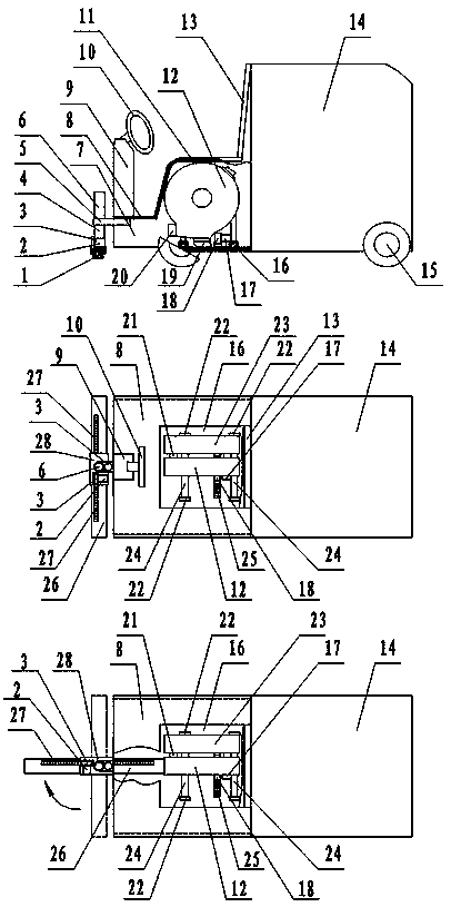
[0020] figure 1In the middle is the overall structure diagram of the reel type automatic cleaning and mopping machine. figure 1 The upper picture in the middle is the front view, the second row is the top view, and the lower picture is the situation when the mop turns to dock with the agitating shell. A mop is installed horizontally in front of the car body. Car body middle part is equipped with seat 11, and seat 11 front lower side is fixedly equipped with pedal 8. The lower side of the pedal 8 is fixedly equipped with a tube base frame 5, and the tube column 4 is installed at the front end of the tube base frame 5. A bracket shell 6 is installed on the pipe string 4 . The lower part of the pipe column is connected with the tank shell 28, and the translation motor 2 and the gear 3 are installed on the tank shell 28. The plate frame 26 on the mopping handkerchief is installed in the groove shell 28. A rack 27 is installed on the plate frame 26 . The handkerchief strip 1 ...


PUM


Abstract

The invention discloses a reeling-type automatic cleaning floor mopping machine. The reeling-type automatic cleaning floor mopping machine comprises mop cloth, agitation washing mechanisms, a vehiclebody, a rotating device, a lifting device, a translation mechanism and a transferring device; mop strips of the mop cloth are connected to the lower portions of base sheets. Slide channels are formedin the two sides of a plate shelf of the mop cloth, and the base sheets are inserted in the slide channels. A rotary wheel, a rotary ring, a rotary ring cover and an agitation washing plate are installed in each agitation washing mechanism. Slide channels are formed in the outer circles of the rotary wheels. A hanging clamp and a pushing clamp are installed on each rotary ring. The two agitation washing mechanisms are in alternate butt joint with the end of the mop cloth, the dirty base sheet cloth strips in the plate shelf are pulled out, and washed clear base sheet cloth strips are insertedinto the plate shelf. During washing, the hanging clamps pull the dirty mop cloth base sheets into the slide channels of the rotary wheels, the rotary wheels rotate forwardly and reversely, and the agitation washing plates agitation-washes the cloth strips; when the agitation washing plates are retracted, the rotary wheels quickly rotate to achieve dewatering. After washing is finished, the rotaryrings rotate reversely to insert the base sheets into the slide channels of the plate shelf. The mop cloth is sent back to the original place to continue to mop the floor. The mop cloth can be automatically cleaned and dewatered. The reeling-type automatic cleaning floor mopping machine is suitable for quickly mopping stations, subways, tunnels, squares and public places, and the working efficiency and the cleaning quality are improved.

Description

technical field [0001] The invention belongs to the field of environmental protection machinery, in particular to a reel type automatic cleaning and mopping machine. Background technique [0002] The present elongated frame-type mopping handkerchief is a very widely used mopping tool. Especially in residential quarters, shopping malls, office spaces, schools, hospitals, most of the cleaners wipe the floor with a long strip frame mop. The cleaning of this strip-shaped mop has been a troublesome thing for a long time. One is that the mop is too long. If there is no special rectangular cleaning pool, the general basin cannot fit it. Flushing with tap water is a waste of water and not clean. Moreover, dehydration after washing is also very troublesome, and the dehydration effect is very poor. Workers dripping water while walking with a mop. There is a strip-shaped handkerchief automatic cleaning vehicle, patent application number: 2017107145202, which adopts a cleaning pool...

Claims


Application Information

Patent Timeline
Patent Type & Authority Applications(China)
IPC IPC(8): A47L11/28A47L11/40
CPCA47L11/28A47L11/40A47L11/4011A47L11/4036
Inventor 邹家鸿邹家福邹永平张文彬邹家华胡冬梅
Owner SUINING CHANGFENG MECHANICAL TECH
Why Eureka
Try Eureka