Airtightness detector for pump of pressure vessel

A pressure vessel and testing machine technology, which can be used in liquid/vacuum measurement for liquid tightness, and by detecting the appearance of fluid at the leak point, etc., can solve the problems of low degree of automation, high labor consumption, and low detection efficiency, etc. Achieve the effect of improving the degree of automation and realizing recycling

Inactive Publication Date: 2018-11-20
邢明的
View PDF4 Cites 0 Cited by
  • Summary
  • Abstract
  • Description
  • Claims
  • Application Information

AI Technical Summary

Problems solved by technology

[0002] In industrial production activities, all kinds of pump bodies are responsible for very important engineering tasks. At present, the pump bodies are produced and processed according to the requirements of the design drawings. Due to the large number of manufacturers and the variety and complexity of equipment types, the detection methods in the production process , The detection equipment is relatively small, and it is difficult to effectively guarantee the product quality and performance without effective quality supervision, so that there are great hidden dangers in the use of the pump body. The general air tightness detection method is the bubble method, that is, The so-called water immersion detection is mainly to realize air tightness detection by immersing the container in water to check whether it leaks air. The traditional detection method is to manually immerse the pump body in water, manually clamp it, and manually pour water and drain it. For example, the application number is 201510111220.6 Published a "A Kind of Air Tightness Testing Device", which mainly includes a frame, a horizontal transmission device, a vertical transmission device, a fixing device, and a water tank. The water in the water tank is poured manually and needs to be drained manually after the test is completed. , this method has low degree of automation, low detection efficiency, and large manpower consumption, so a new type of air tightness testing machine is needed

Method used


Image

  • Airtightness detector for pump of pressure vessel
  • Airtightness detector for pump of pressure vessel
  • Airtightness detector for pump of pressure vessel

Examples


Embodiment

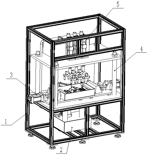
[0015] Example: such as figure 1 , figure 2 , image 3 , Figure 4 A pressure vessel pump body air tightness testing machine shown includes a main frame body 1, a water supply and drainage unit 2, a clamping and fixing unit 3, a mounting frame 4, and a pressing unit 5. The main frame body 1 is used as a whole The installation standard of the mechanism is that the installation frame 4 is fixed in the middle of the main frame body 1, the lower part of the water supply and drainage unit 2 is installed on the bottom side of the main frame body 1, the upper part is installed on the top side of the installation frame 4, and the clamping and fixing unit 3 is installed on the On the bottom plate of the mounting frame 4 , the pressing unit 5 is installed on the top plate of the mounting frame 4 .

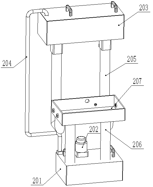
[0016] The water supply and drainage unit 2 includes a lower water tank 201, a water pump 202, an upper water tank 203, a water inlet pipe 204, a water outlet pipe 205, a drain pipe 206,...


PUM


Abstract

The invention provides an airtightness detector for a pump of a pressure vessel. The detector comprises a main rack, a water supply and drainage unit, a clamping and fixing unit, a mounting rack and acompression unit, the main rack serves as an installation reference of the whole mechanism, the mounting rack is fixed in the middle of the main rack, the lower of the water supply and drainage unitis mounted in the bottom side of the main rack, the upper of the water supply and drainage unit is installed in the top side of the mounting rack, the clamping and fixing unit is installed on a base plate of the mounting rack, and the compression unit is mounted on a top plate of the mounting rack. Thus, the pump is fixed by the clamping and fixing unit, and compressed tightly by the compression unit, water for detection is injected into a water tank and drained after detection by the water supply and drainage unit, manual pump clamping and water drainage are avoided, the automatic degree is improved, and the detection water can be used cyclically.

Description

technical field [0001] The invention relates to the technical field of airtightness detection of small pressure vessels, in particular to a pressure vessel pump body airtightness detection machine. Background technique [0002] In industrial production activities, all kinds of pump bodies are responsible for very important engineering tasks. At present, the pump bodies are produced and processed according to the requirements of the design drawings. Due to the large number of manufacturers and the variety and complexity of equipment types, the detection methods in the production process , The detection equipment is relatively small, and it is difficult to effectively guarantee the product quality and performance without effective quality supervision, so that there are great hidden dangers in the use of the pump body. The general air tightness detection method is the bubble method, that is, The so-called water immersion detection is mainly to realize air tightness detection by...

Claims


Application Information

Patent Timeline
Patent Type & Authority Applications(China)
IPC IPC(8): G01M3/06
Inventor 不公告发明人
Owner 邢明的
Why Eureka
Try Eureka