Heat dissipating fin and installation method thereof

An installation method and heat sink technology, which are applied in the direction of modification by conduction heat transfer, cooling/ventilation/heating renovation, electrical components, etc. , conduction and bonding and other issues, to achieve the effect of good shielding effect

Pending Publication Date: 2018-11-16
深圳市金卓立五金制品有限公司
View PDF0 Cites 3 Cited by
  • Summary
  • Abstract
  • Description
  • Claims
  • Application Information

AI Technical Summary

Problems solved by technology

The bottom of the heat sink is pasted with conductive foam, but most of the conductive foam on the market is an integrated structure, which makes it inconvenient to splice and disassemble the conductive foam, and it is not convenient for the conductive foam to fill the gap, conduct electricity and bond. The use of integrated conductive foam is easy to cause waste of resources when cutting, and it is not conducive to partial replacement. Moreover, it is easy to form high temperature after long-term use, which makes it easy to deform when used at high temperature for a long time, thus affecting the conductive foam. Cotton shielding

Method used


Image

  • Heat dissipating fin and installation method thereof
  • Heat dissipating fin and installation method thereof
  • Heat dissipating fin and installation method thereof

Examples


Embodiment Construction

[0033] The following will clearly and completely describe the technical solutions in the embodiments of the present invention with reference to the accompanying drawings in the embodiments of the present invention. Obviously, the described embodiments are only some, not all, embodiments of the present invention. All other embodiments obtained by persons of ordinary skill in the art based on the embodiments of the present invention belong to the protection scope of the present invention.

[0034] According to an embodiment of the present invention, a heat sink is provided.

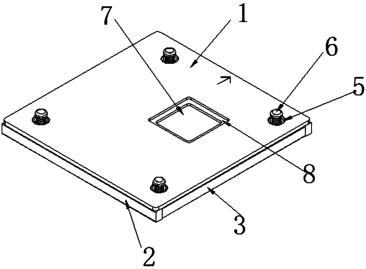
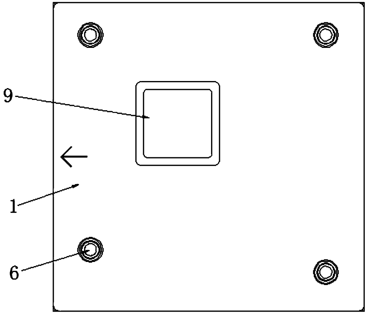
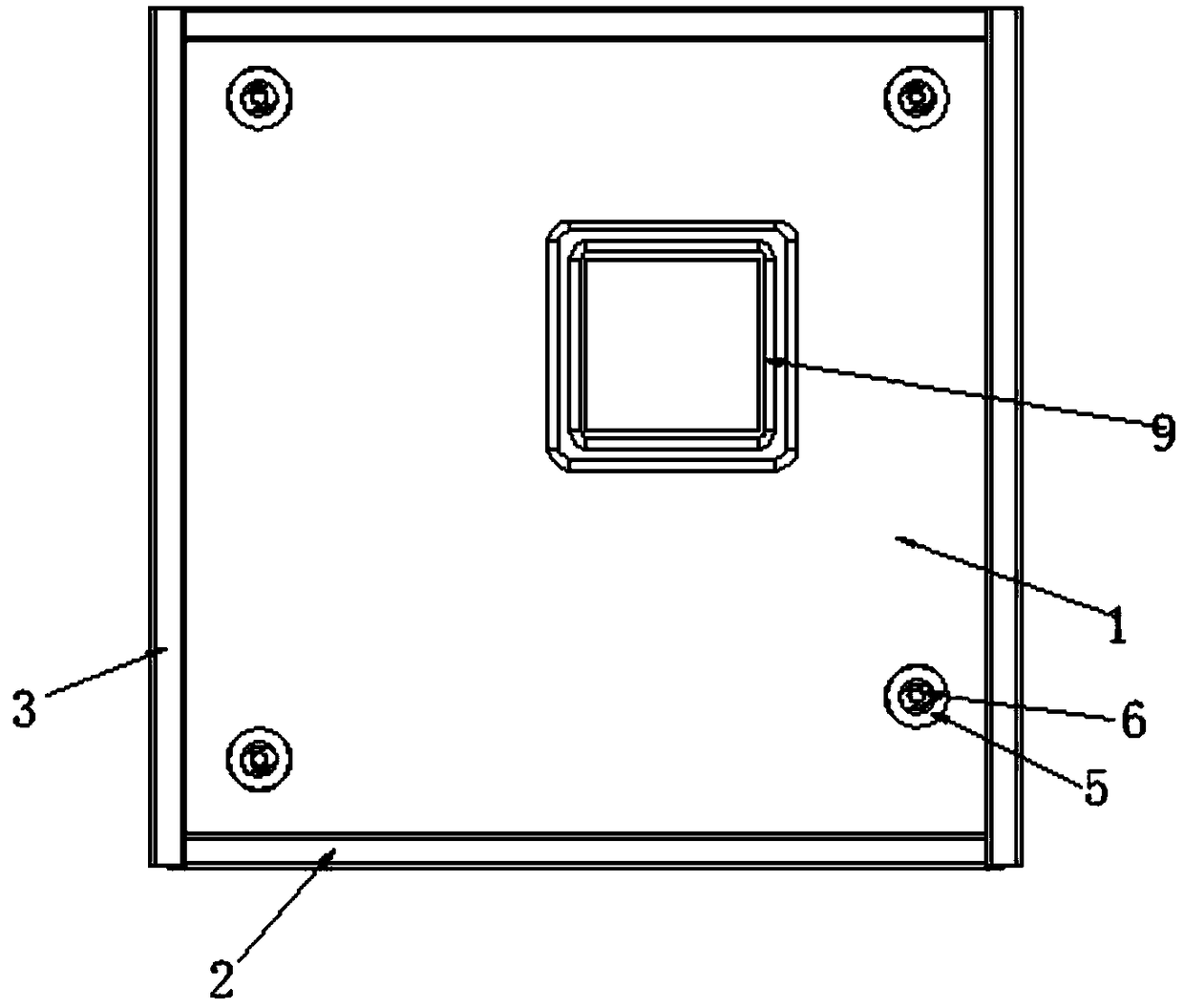
[0035] Such as Figure 1-8 As shown, a heat sink includes a heat sink 1, a plurality of conductive foam 1 2 and conductive foam 2 3, and the bottom of the heat sink 1 is provided with symmetrical conductive foam 1 on both sides. 2. The bottom and other sides of the heat dissipation plate 1 are provided with symmetrical conductive foam 2 3, wherein, the four ends of the corners of the heat dissipation plate...


PUM


Abstract

The invention discloses a heat dissipating fin, comprising a heat dissipating plate and a plurality of conductive foams 1 and conductive foams 2, wherein two sides of the bottom of the heat dissipating plate are provided with symmetric conductive foams 1, and the other two sides of the bottom of the heat dissipating plate are provided with symmetrical conductive foams 2; the four ends of the corners of the heat dissipating plate are provided with mounting holes, and the mounting holes are provided with sleeves in a sleeving manner, the sleeves fixedly connect the heat dissipating plate with external equipment through fasteners, one side of the heat dissipating plate is provided with a through hole, the upper portion of the through hole is provided with a clamp slot 1 extending to the inside of the through hole, the clamp slot 1 is internally fastened with a thermal conductive silica gel matched with the clamp slot 1, and the thermal conductive silica gel penetrates through the throughhole and is matched with the through hole.

Description

technical field [0001] The invention relates to the technical field of heat sinks, in particular to a heat sink and an installation method thereof. Background technique [0002] Generally, the heat sink should be coated with a layer of heat-conducting silicone grease on the contact surface between the electronic components and the heat sink during use, so that the heat emitted by the components can be more effectively transferred to the heat sink, and then dissipated into the surrounding air through the heat sink. The bottom of the heat sink is pasted with conductive foam, but most of the conductive foam on the market is an integrated structure, which makes it inconvenient to splice and disassemble the conductive foam, and it is not convenient for the conductive foam to fill the gap, conduct electricity and bond. The use of integrated conductive foam is easy to cause waste of resources when cutting, and it is not conducive to partial replacement. Moreover, it is easy to form...

Claims


Application Information

Patent Timeline
Patent Type & Authority Applications(China)
IPC IPC(8): H05K7/20H05K9/00
CPCH05K7/2039H05K7/20463H05K9/0016
Inventor 钟裕锋
Owner 深圳市金卓立五金制品有限公司
Why Eureka
Try Eureka