Auxiliary machine for pipe connection in gas-insulated metal-enclosed transmission line

A gas-insulated metal and power transmission line technology, which is applied to cable laying equipment and other directions, can solve the problems that the adjustment bracket cannot complete the installation and assembly tasks, the frame width is large, and the installation space is small, so as to meet the pipeline adjustment and installation requirements, meet the Pipeline adjustment and installation requirements, the effect of ensuring stability

Active Publication Date: 2018-11-16
STATE GRID CORP OF CHINA +4
View PDF7 Cites 0 Cited by
  • Summary
  • Abstract
  • Description
  • Claims
  • Application Information

AI Technical Summary

Problems solved by technology

The existing adjustment bracket adopts a structure in which the moving mechanism is placed under the pipe bracket, but due to the complexity of the moving mechanism and the large width of the frame, it cannot meet the small installation space between the bellows and the fixed bracket during the installation of the pipe gallery. As a result, the center of gravity of the pipe unit with bellows at the end deviates during the adjustment and installation process, resulting in the instability of the pipe unit
[0003] At the same time, if Figure 8 and Figure 9 As shown, the gas-insulated metal-sealed transmission line is a three-layer pipeline structure. When the adjustment bracket of the prior art is used, due to the distance limitation between two adjacent layers of pipelines, the adjustment bracket may interfere with the pipeline, resulting in the adjustment bracket The installation and assembly tasks cannot be completed, that is, the existing adjustment brackets cannot meet the assembly requirements of multi-layer pipeline structures with two or more layers

Method used


Image

  • Auxiliary machine for pipe connection in gas-insulated metal-enclosed transmission line
  • Auxiliary machine for pipe connection in gas-insulated metal-enclosed transmission line
  • Auxiliary machine for pipe connection in gas-insulated metal-enclosed transmission line

Examples


Embodiment Construction

[0028] In order to make the purpose, technical solution and advantages of the present invention clearer, the technical solution of the present invention will be clearly and completely described below in conjunction with specific embodiments of the present invention and corresponding drawings. Apparently, the described embodiments are only some of the embodiments of the present invention, but not all of them. Based on the embodiments of the present invention, all other embodiments obtained by persons of ordinary skill in the art without making creative efforts fall within the protection scope of the present invention.

[0029] The technical solutions provided by the embodiments of the present invention will be described in detail below in conjunction with the accompanying drawings.

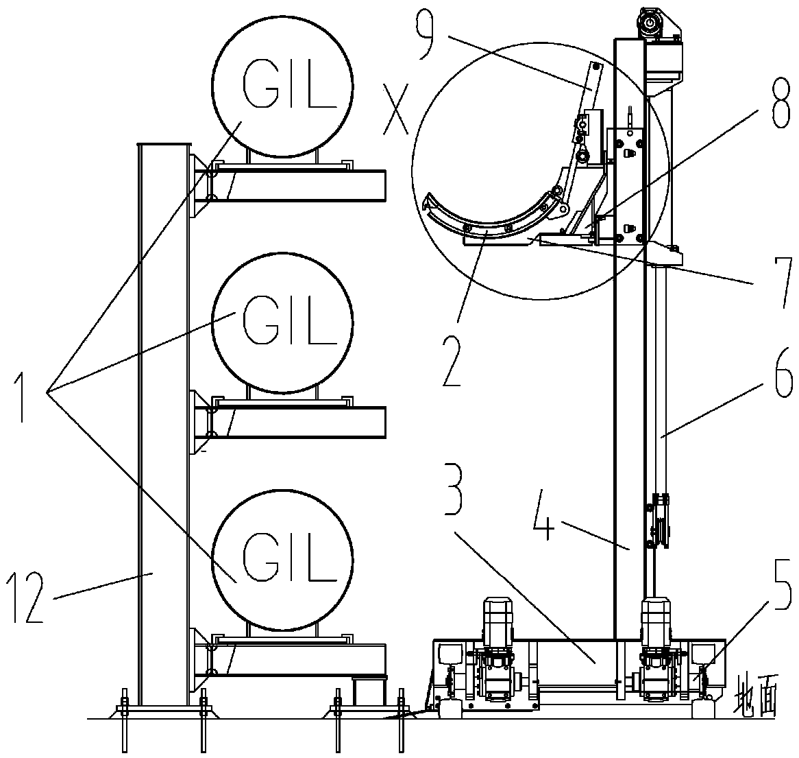
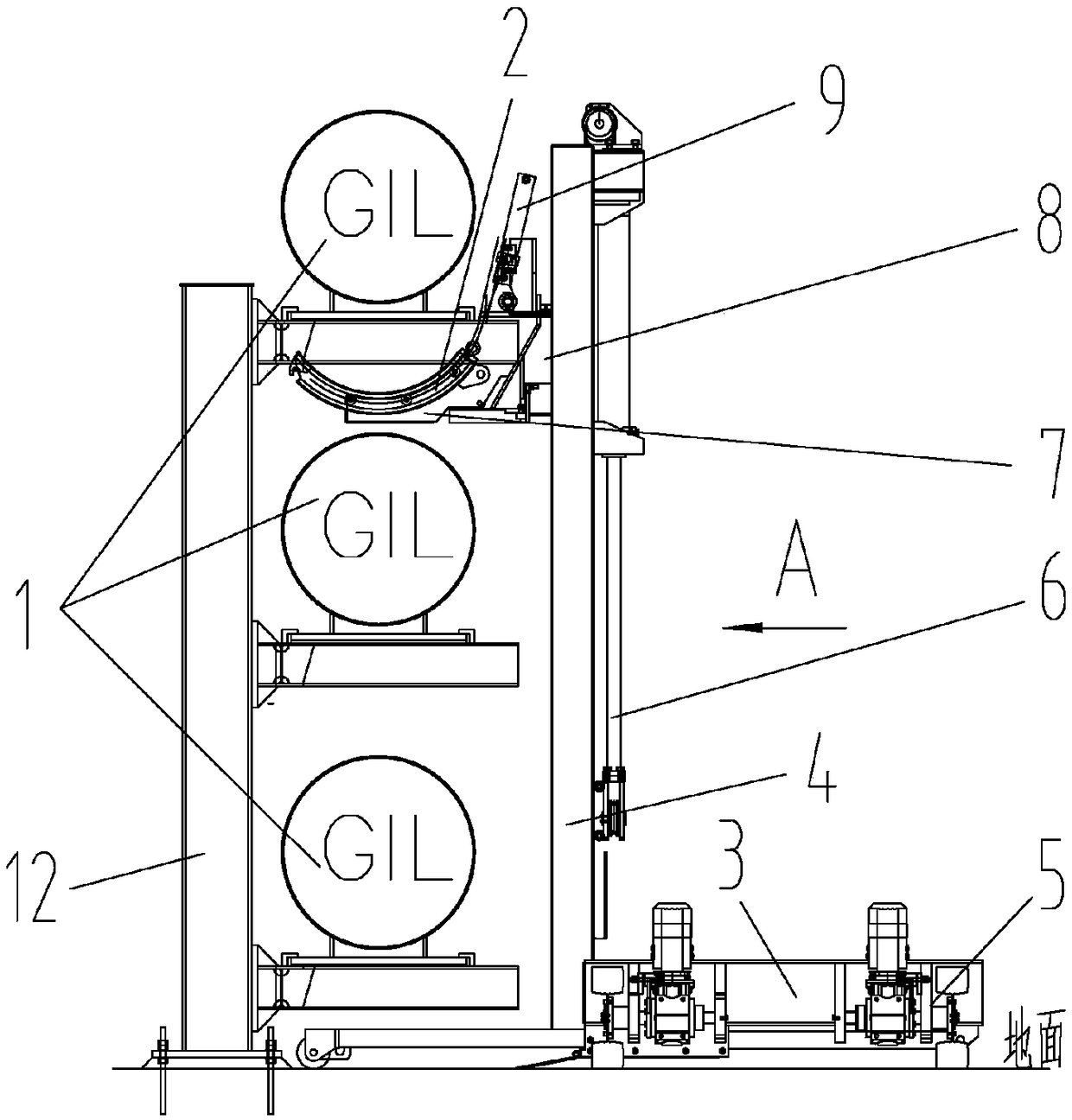
[0030] figure 1 A schematic diagram of the structure of an auxiliary device for pipeline connection in a gas-insulated metal-enclosed transmission line provided by an embodiment of the present in...


PUM


Abstract

The invention discloses an auxiliary machine for pipe connection in a gas-insulated metal-enclosed transmission line. The auxiliary machine includes a pipe holder, and further includes a support baseand a vertical column mounted on the support base for supporting the pipe holder. The support base is provided with a pushing mechanism for pushing the vertical column. The vertical column is providedwith a lifting mechanism for driving the pipe holder to move up and down, a radial movement mechanism and an axial movement mechanism. The radial movement mechanism and the axial movement mechanism are used for driving the radial movement and the axial movement of the pipe holder respectively. The radial movement mechanism is provided with a rotation mechanism for realizing the rotational motionof the pipe holder. The lifting mechanism, the axial movement mechanism and the radial movement mechanism are all disposed outside the pipe holder. The auxiliary machine can meet the requirement for asmall space between a bellows and a fixing bracket and the requirement for a short distance between adjacent pipes when a multilayer pipeline structure type is used, can realize the all-round adjustment of a pipe unit, and ensures the stability of the pipe unit in an adjustment process.

Description

technical field [0001] The invention relates to the technical field of gas-insulated metal-enclosed transmission lines, in particular to an auxiliary device for connecting pipelines in gas-insulated metal-enclosed transmission lines. Background technique [0002] Gas-insulated metal-enclosed transmission line (Gas-insulated Metal-enclosed Transmission Line, GIL) has a large transmission capacity and is capable of ultra-high voltage and large-capacity transmission, and is widely used in power transmission systems. In gas-insulated metal-enclosed transmission lines, in order to reduce the number of sealing surfaces, according to engineering technical requirements, it is necessary to install bellows at the end of the tube unit of the transmission pipeline. Figure 8 It is a schematic diagram of the layout of the pipe gallery of the closed transmission line with the gas insulation technology in the prior art, wherein the pipe gallery is a three-layer pipeline type. Figure 9 for...

Claims


Application Information

Patent Timeline
Patent Type & Authority Applications(China)
IPC IPC(8): H02G1/08
CPCH02G1/08
Inventor 郝建光范江波陈晓敏宋帅孙岗李新建侯镭马卫华张鹏飞葛栋张宁肖峰刘波肖树陆东生陈松涛钱玉华仝进科于潜杜玉龙米勇
Owner STATE GRID CORP OF CHINA
Why Eureka
Try Eureka