
Three Arm Circularly Polarized Antenna

A technology of circularly polarized antenna and circular ring, which is applied in the field of communication, can solve the problems of circularly polarized antenna with complex structure, low gain of circularly polarized antenna, increased volume, etc., and achieve strong practicability, easy manufacture, and simple antenna structure Effect

Active Publication Date: 2020-01-17
UNIV OF ELECTRONICS SCI & TECH OF CHINA
View PDF8 Cites 0 Cited by
  • Summary
  • Abstract
  • Description
  • Claims
  • Application Information

AI Technical Summary

Problems solved by technology

[0004] Therefore, the gain of the conventional circularly polarized antenna is low. In order to improve the antenna gain, methods such as using multi-feed point multiple structures or adding reflectors are proposed, but these methods make the structure of the circularly polarized antenna more complicated and the volume increases.

Method used


Image

  • Three Arm Circularly Polarized Antenna
  • Three Arm Circularly Polarized Antenna
  • Three Arm Circularly Polarized Antenna

Examples


Embodiment Construction

[0029] Embodiments of the present invention are described below through specific examples, and those skilled in the art can easily understand other advantages and effects of the present invention from the content disclosed in this specification. The present invention can also be implemented or applied through other different specific implementation modes, and various modifications or changes can be made to the details in this specification based on different viewpoints and applications without departing from the spirit of the present invention.

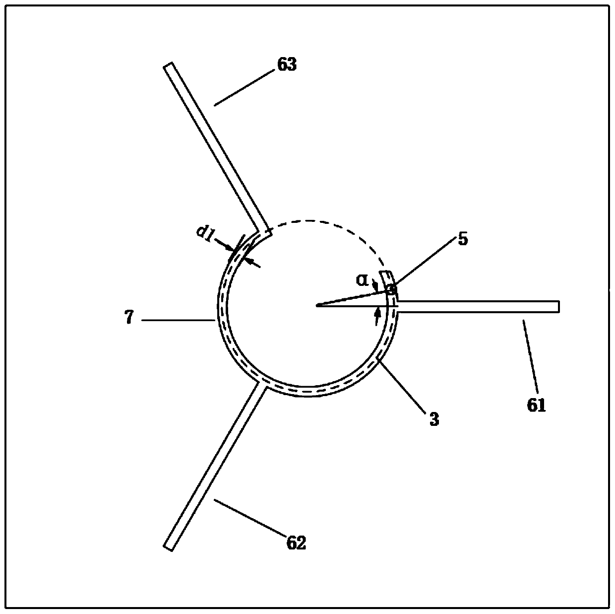
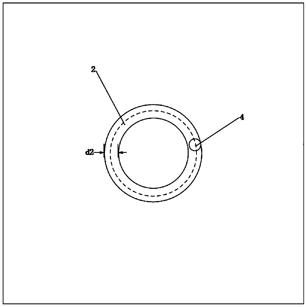
[0030] A three-arm circularly polarized antenna, including a dielectric substrate 1, a radiation patch 3, and a ground plane 2, the radiation patch 3 and the ground plane 2 are symmetrically arranged up and down along the center line of the dielectric substrate 1, and the radiation patch 3 is located on the dielectric substrate 1 The upper surface of the upper surface, the ground plate 2 is below the dielectric substrate 1, and the rad...


PUM


Abstract

The invention provides a three-arm circularly polarized antenna, which includes a dielectric substrate, a radiation patch and a grounding plate, and the radiation patch includes a feeding microstrip line patch and three metal stickers on the outer circumference of the feeding microstrip line patch Slice arm, feed microstrip line patch is a circular ring with a gap, the angle between two adjacent metal patch arms is 120 degrees; the radiation patch is provided with a radiation patch circular groove, and the ground plate It is a circular ring with a circular groove on the ground plate. The invention solves the problem of low gain in the traditional circularly polarized antenna design method, which is different from the traditional circularly polarized antenna design that uses two directions that are orthogonal to each other and have a phase difference of 90°. The electric field vector composition mode of the present invention, the present invention adopts the electric field vector that three direction intervals are 120° and the phase difference is 120° to form circular polarization, the electric field vector after synthesis is 1.5 times of the traditional design method, and the axis in the main radiation direction The ratio is less than 3dB, the angle is about 60°, the gain is 2dBi, the antenna structure is simple, and it is easy to manufacture.

Description

technical field [0001] The invention relates to the technical field of communication, in particular to a three-arm circularly polarized antenna. Background technique [0002] With the rapid development of modern electronic information technology and the increasing application of radio equipment, antennas, as a device for energy conversion and directional radiation / reception of electromagnetic waves, have received extensive attention and in-depth research. In recent years, antennas have been widely used in many fields, not only in mobile communications, satellite communications, navigation telemetry and many other military fields, but also in satellite navigation, modern mobile communications, biomedicine, radio and television and other civilian fields. Circularly polarized antennas have many advantages over linearly polarized antennas: they have advantages in anti-interference, anti-fading, and anti-multipath effects; they are orthogonal to the direction of rotation; they r...

Claims


Application Information

Patent Timeline
Patent Type & Authority Patents(China)
IPC IPC(8): H01Q1/38H01Q1/48H01Q1/50
CPCH01Q1/38H01Q1/48H01Q1/50
Inventor 杨德强胡鉴中杨鑫毛宁馨孙凯杨天明
Owner UNIV OF ELECTRONICS SCI & TECH OF CHINA
Learn More