
Integrated LLC transformer

A technology of LLC transformer and accommodating part, which is applied in the field of transformers, can solve the problems such as difficult adjustment of leakage inductance, poor magnetic coupling ability, and increased leakage inductance, so as to improve the stability of electrical performance and safety factor, and improve the stability of electrical appliances As well as the safety factor and the effect of improving stability

Pending Publication Date: 2018-11-16
SUINING PUSI ELECTRONICS
View PDF1 Cites 0 Cited by
  • Summary
  • Abstract
  • Description
  • Claims
  • Application Information

AI Technical Summary

Problems solved by technology

However, due to the large resonance inductance required for resonance, the leakage inductance of the transformer is often very small. Usually, the distance between the primary coil and the secondary coil is increased, so that the coupling coefficient between the primary coil and the secondary coil becomes smaller, achieving an increase. The purpose of large leakage inductance, but this will often make the volume of the transformer larger and the magnetic coupling capability poor
[0004] The existing technology also has a solution to increase the leakage inductance of the transformer by adding a magnetic core between the primary coil and the secondary coil. For example, the Chinese invention patent application CN201610995019.3 discloses a method by adding a A leakage magnetic core forms a side branch magnetic flux, thereby increasing the leakage inductance, but the leakage inductance is not easy to adjust in this way

Method used


Image

  • Integrated LLC transformer
  • Integrated LLC transformer
  • Integrated LLC transformer

Examples


Embodiment Construction

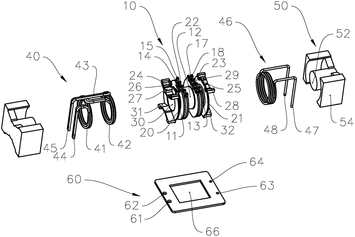
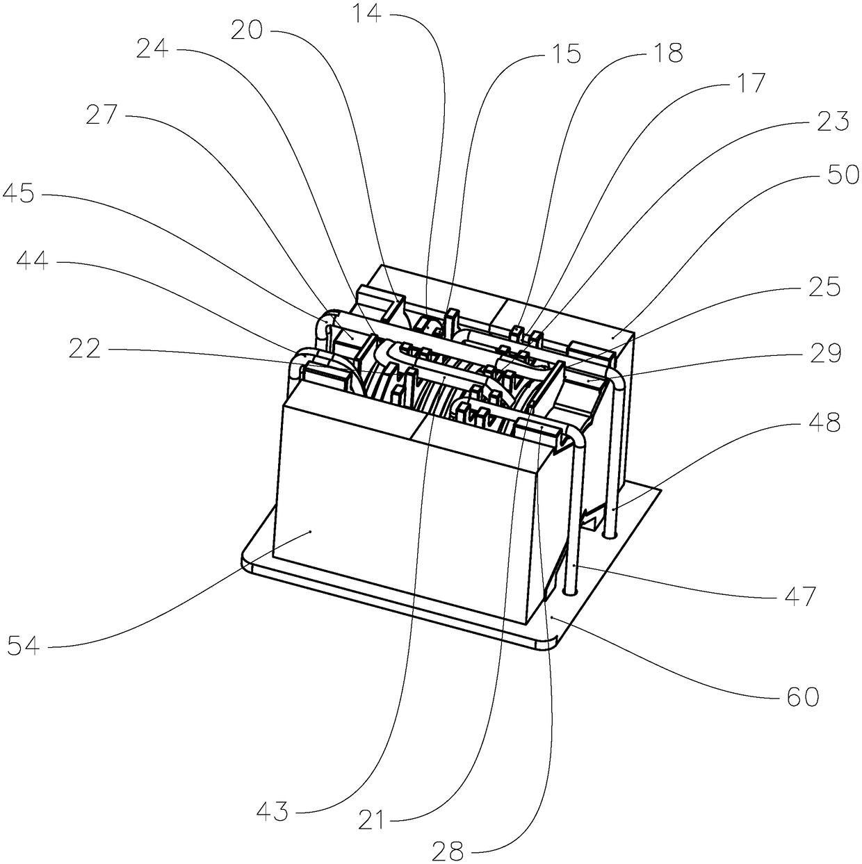
[0029] see figure 2 , the integrated LLC transformer of this embodiment includes a magnetic core 50 , a bobbin 10 , a primary coil 40 and a secondary coil 46 .

[0030] Wherein, the magnetic core 50 is a solid magnetic core, which is composed of a pair of magnetic cores, wherein the magnetic core 50 includes a magnetic core center column 52 and a magnetic core side column 54, and the magnetic core center column 52 is located in the middle of the magnetic core side column 54 Position, the magnetic core center column 52 is placed in the magnetic core channel 30, and the magnetic core side column 54 is used to cover most of the skeleton 10, to increase the inductance of the entire transformer, and also to play the role of magnetic shielding.

[0031] The primary coil 40 includes a first partial coil 41, a second partial coil 42, a connecting partial coil 43, a first signal pin 44, and a second signal pin 45, wherein the connecting partial coil 43 is connected to the first partia...


PUM


Abstract

The invention provides an integrated LLC transformer. The integrated LLC transformer comprises a primary coil, a secondary coil, a framework and a magnetic core, the framework comprises a magnetic core channel, and the magnetic core is arranged in the magnetic core channel. The integrated LLC transformer is characterized in that the primary coil comprises a first part coil, a second part coil anda connection part coil, the connection part coil is connected with the first part coil and the second part coil separately, and a first containing part, a second containing part and a third containingpart are arranged at the exterior of the magnetic core channel; a first insulation part and a second insulation part are further arranged at the exterior of the magnetic core channel, the first insulation part is located between the first containing part and the second containing part, and the second insulation part is located between the second containing part and the third containing part; thefirst part coil is arranged on the first containing part, the second part coil is arranged on the third containing part, and the secondary coil is arranged on the second containing part. The integrated LLC transformer has the advantages that the magnitude of leakage inductance can be adjusted, and the stability is good.

Description

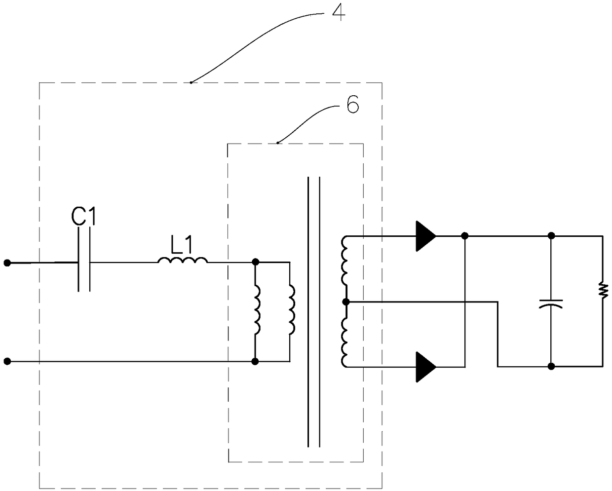
technical field [0001] The present invention relates to the field of transformers, in particular to integrated LLC transformers. Background technique [0002] In order to facilitate the resonance debugging and stability of the entire power supply, a general resonance circuit is added with a resonance inductor and capacitor to adjust the resonance circuit. see figure 1 , the existing LLC resonant transformer includes a resonant circuit 4, the resonant circuit 4 includes a capacitor C1, a resonant inductor L1 and a transformer 6, the capacitor C1 is connected in series with the resonant inductor L1, and the resonant inductor L1 is connected in series with the transformer 6, through the capacitor C1, the resonant inductor L1 and The resonance between the inductances in the transformer 6 forms a resonant circuit 4 for frequency adjustment to achieve a constant output voltage. However, this will make the structure of the power supply complicated, the volume increased, the elect...

Claims


Application Information

Patent Timeline
Patent Type & Authority Applications(China)
IPC IPC(8): H01F27/26H01F27/28H01F27/29H01F27/30
CPCH01F27/266H01F27/2823H01F27/2828H01F27/29H01F27/306
Inventor 王先锋陈乾李良如邹力鲁陈林翠芬魏汉君
Owner SUINING PUSI ELECTRONICS
Learn More