
Optical module

A technology of optical modules and optical devices, which is applied in the field of optical communication, and can solve the problems of affecting the signal transmission performance of optical modules, inability to fit tightly, and unreliable fixing of shielding plate 20 and bracket 10, etc.

Inactive Publication Date: 2018-11-16
HISENSE BROADBAND MULTIMEDIA TECH
View PDF6 Cites 4 Cited by
  • Summary
  • Abstract
  • Description
  • Claims
  • Application Information

AI Technical Summary

Problems solved by technology

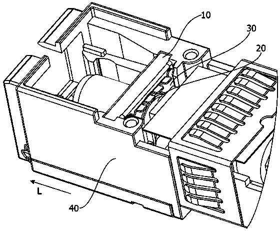
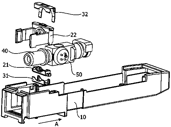
However, there are deficiencies in this shielding method. On the one hand, there is a gap between the shielding plate 30 and the claw 10, which cannot be closely attached to the surface of the claw 10, so that the electromagnetic signal passes through the gap between the shielding plate 30 and the claw 10. On the other hand, being clamped in the bracket, the fixation between the shielding plate 20 and the bracket 10 is not firm, so that the shielding plate 30 is in the length direction of the optical module (see figure 1 There is an active space in the middle A direction), and then the shielding plate 30 is in contact with the metal optical device 20 so that a short circuit occurs, which will directly affect the signal transmission performance of the optical module

Method used


Image

  • Optical module
  • Optical module
  • Optical module

Examples


Embodiment Construction

[0029] Reference will now be made in detail to the exemplary embodiments, examples of which are illustrated in the accompanying drawings. When the following description refers to the accompanying drawings, the same numerals in different drawings refer to the same or similar elements unless otherwise indicated. The implementations described in the following exemplary examples do not represent all implementations consistent with the present disclosure. Rather, they are merely examples of apparatuses and methods consistent with aspects of the present disclosure as recited in the appended claims.

[0030] The terms "comprising" and "having" and any variations thereof in the description and claims of the present invention and the drawings are intended to cover a non-exclusive inclusion. For example, a process, method, system, product or device comprising a series of steps or units is not limited to the listed steps or units, but optionally also includes unlisted steps or units, or...


PUM


Abstract

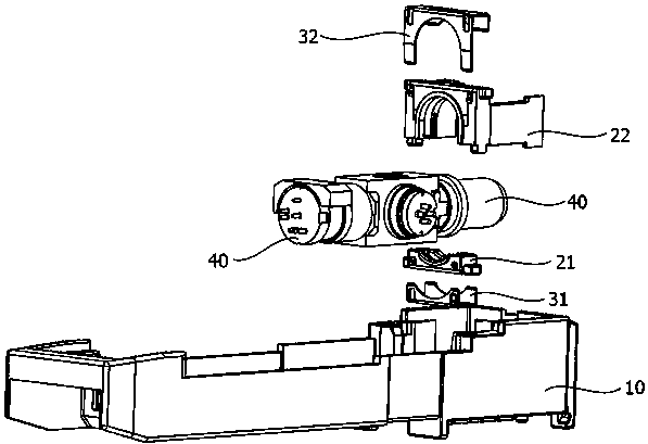
The invention provides an optical module. The optical module comprises a base, a support assembly, a shielding assembly, an optical device and an optical fiber adapter, the optical device is connectedwith the optical fiber adapter, the support assembly is made of a non-metallic material and comprises a first support and a second support, the first support is arranged on the base, a chuck arrangedon the optical fiber adapter is arranged in an accommodating chamber formed by enclosure of the first support and the second support, the shielding assembly is made of a metallic material and comprises a first shielding sleeve and a second shielding sleeve, the first shielding sleeve is connected with the first support, and the second shielding sleeve is connected with the second support. After the support assembly is fixedly arranged on the base, the shielding assembly is arranged on the support assembly for supporting the optical fiber adapter to enable the shielding assembly to be stably connected in the optical module, short circuit caused by contact between the optical fiber adapter and the shielding assembly due to instable fixing is prevented, the electromagnetic shielding performance in the optical module is guaranteed, and the transmission stability of optical signals of the optical module is improved.

Description

technical field [0001] The invention relates to the technical field of optical communication, in particular to an optical module. Background technique [0002] With the improvement of the performance of the optical module, it is required that the optical device inside the optical module and the optical port of the optical fiber plug in the optical module are electromagnetically shielded to prevent the electromagnetic signal emitted by the optical device from being emitted to the outside of the optical module, thereby affecting the optical fiber. The transmission quality of the communication. See figure 1 As shown, at present, a shielding plate 30 is usually provided between the claw 10 for fixing the optical device and the optical device 20, the shielding plate 30 abuts on the bracket 40, and the clamping of the claw 10 and the optical device 20 realizes the shielding plate 30 in the length direction of the optical module (see figure 1 In the direction A), the shielding p...

Claims


Application Information

Patent Timeline
IPC IPC(8): G02B6/42
Inventor 陈金磊刘寅龙司宝峰
Owner HISENSE BROADBAND MULTIMEDIA TECH
Learn More